EVCO EV9376J9 User Manual
Page 7
Evco S.p.A. • Code 1049376E00 • page 7/8
18
WORK SET-POINT AND CONFIGURATION PARAMATERS
18.1
Work set-point
MIN
MAX
U.M.
DEF.
r1
r2
°C/°F (1) 150
r7
r8
°C/°F (1) 150
r1
r2
°C/°F (1) 150
r1
r2
°C/°F (1) 150
r1
r2
°C/°F (1) 150
r1
r2
°C/°F (1) 150
18.2
Configuration parameters
PARAM. MIN
MAX
U.M.
DEF.
SP1
r1
r2
°C/°F (1) 150
SP2
r7
r8
°C/°F (1) 150
SP3
r1
r2
°C/°F (1) 150
SP4
r1
r2
°C/°F (1) 150
SP5
r1
r2
°C/°F (1) 150
SP6
r1
r2
°C/°F (1) 150
PARAM. MIN
MAX
U.M.
DEF.
CA1
-25/-50 25/50 °C/°F (1) 0
CA2
-25/-50 25/50 °C/°F (1) 0
P0
0
1
- - - -
0
P2
0
1
- - - -
0
P4
0
1
- - - -
0
P5
0
3
- - - -
0
P6
0
6
- - - -
6
PARAM. MIN
MAX
U.M.
DEF.
r0
1
99
°C/°F (1) 5
r1
0
r2
°C/°F (1) 50
r2
r1
999
°C/°F (1) 350
r4
0
99
°C/°F (1) 10
r7
0
r8
°C/°F (1) 50
r8
r7
999
°C/°F (1) 350
r11
0
1
- - - -
1
r13
0
240
min
240
r15
0
1
- - - -
0
r16
0
1
- - - -
0
r17
0
1
- - - -
0
PARAM. MIN
MAX
U.M.
DEF.
d1
00:01 24:00 h:min
00:30
d3
00:01 24:00 h:min
01:00
d4
00:01 24:00 h:min
00:30
d5
00:01 24:00 h:min
00:30
PARAM. MIN
MAX
U.M.
DEF.
t0
0
1
- - - -
0
t1
0
250
s
1
t2
1
250
ds (8)
10
t5
0
1
- - - -
0
PARAM. MIN
MAX
U.M.
DEF.
c1
1
60
min
5
c4
-1
120
s
15
c5
0
60
min
20
c6
0
60
min
20
c7
00:00 60:00 min:s
00:30
c8
0
1
- - - -
1
WORK SET-POINT
work set-point of the timed cooking phase
set pint at core
work set-point of the core cooking phase
work set-point of the steam cooking phase
work set-point of the grill cooking phase
work set-point of the continuous cooking phase
WORK SET-POINT
work set-point of the timed cooking phase
set pint at core
work set-point of the core cooking phase
work set-point of the steam cooking phase
work set-point of the grill cooking phase
work set-point of the continuous cooking phase
MEASUREMENT INPUTS
chamber probe offset
core probe offset
type of probe (2)
0 = J
1 = K
temperature unit of measurement (3)
0 = °C
1 = °F
enabling the core probe
1 = YES
quantity displayed by the upper part of the display during the on status in progress of normal functioning mode
0 = chamber temperature
1 = work set-point of the phase in progress
2 = core temperature (4)
3 = core set-point (4)
quantity displayed by the lower part of the display during the on status in progress of normal functioning mode
0 = chamber temperature
1 = work set-point of the phase in progress
2 = count of the duration of the cooking phase in progress
3 = day and real time
4 = core temperature (6)
5 = core set-point (6)
6 = most significant quantity for the event in progress:
• “PrEH” during the pre-heating phase
• “rdY” flashing on conclusion of the pre-heating phase
• “End” flashing on conclusion of the cooking phase
• “EndP” flashing on conclusion of the program
• “PAUS” flashes during the suspension of the cooking phase
• count of the duration of the cooking phase, during the timed cooking phase, during the steam cooking phase and during the grill cooking phase
• core temperature during the core cooking phase
• “- - - -” during the continuous cooking phase
MAIN REGULATOR
work set-point differential of the pre-heating phase and of the work set-point of any cooking phase
minimum work set-point of any cooking phase
maximum work set-point of any cooking phase
work set-point of the pre-heating phase (relative to the work set-point of the cooking phase following pre-heating, i.e. “work set-point of the cooking phase following pre-heating + r4”)
core minimum set-point
core maximum set-point
enabling the pre-heating phase
1 = YES
duration of the power cut that occurs during a cooking phase, after exceeding which the count of the duration of the phase is interrupted (7)
enabling of the switch-on of the output for the regulation of the temperature during the grill cooking phase
1 = YES
switch-off of the output for the regulation of the temperature during switch-off of the fan.
1 = YES
switch-on of the grill only once before the conclusion of the grill cooking phase (for the time established with the parameter c11)
1 = YES
DURATION OF THE COOKING PHASES
duration of the timed cooking phase
duration of the core cooking phase during the core probe error
duration of the steam cooking phase
duration of the grill cooking phase
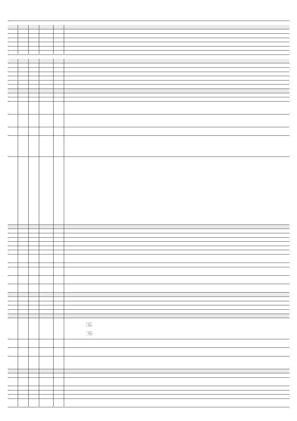
STEAM INJECTION
steam injection functioning mode
0 = pressing the
key will cause the injection of the steam for the time established with parameter t2 or for the entire duration that the key is pressed; the parameter t1
establishes the minimum time that will pass between the two successive injections.
1 = pressing the
key enables the automatic injection of the steam in a cyclical manner (the parameter t2 establishes the duration of switch-on of the injector and the
parameter t1 establishes the duration of switch-off.
if t0 = 0, minimum time that passes between two successive injections
if t0 = 1, duration of injection switch-off
if t0 = 0, minimum injection duration
if t0 = 1, duration of injection switch-on
link between the status of the fan and steam injection
0 = injection of the steam is allowed on the condition that the fan is on
1 = steam injection is allowed on condition that the fan is off (during fan switch-off)
VARIOUS
cycle time for grill switch-on, see also c11
duration of switch-on of the buzzer and the acoustic output on the conclusion of the pre-heating phase and the conclusion of any cooking phase, see also c9
-1 = the buzzer and the acoustic output must be off in manual mode by pressing a key
time that passes between switch-on of the airhole and the conclusion of the steam cooking phase; see also c6
duration of switch-on of the airhole on conclusion of the steam cooking phase; see also c5
duration of airhole switch-on in manual mode
display of the real time in the lower part of the display during the stand-by status
1 = YES