7 microchip development tool compatibility, 1 pinout table by logical pin number – Digilent 410-202P-KIT User Manual
Page 11
chipKIT™ Max32™ Board Reference Manual
Copyright Digilent, Inc. All rights reserved.
Other product and company names mentioned may be trademarks of their respective owners.
Page 11 of 20
3. 7 Microchip Development Tool Compatibility
In addition to being used with the MPIDE, the Max32 board can be used as a more traditional microcontroller
development board using Microchip Development Tools.
Unloaded connector J11 on the left side of the board is used to connect to a Microchip development tool, such as
the PICkit™3, for in-circuit serial programming (ICSP). The holes for JP3 are staggered so that a standard 100-mil-
spaced 6-pin header can be press fit to the board without the need to solder it in place. Any Microchip
development tool that supports the PIC32 microcontroller family, and can be connected via the same 6-pin
interface as the PICkit3, can be used.
Typically, a right-angle male connector is used in J11 so that a PICkit3 can be attached coplanar with the Max32
board. If the connector is loaded from the top, the PICkit3 will be upright (button and LEDs visible). Alternatively,
the connector can be loaded from the bottom. In this case, the PICkit3 will be upside down.
If J11 is loaded from the top, the PICkit3 will interfere with the USB connector and the external power connector. A
short six-wire cable can be used between the PICkit3 and the Max32. If J11 is loaded from the bottom, the PICkit3
won't interfere with the USB and external power connectors.
The Microchip MPLAB
®
IDE or the MPLAB
®
X IDE can be used to program and debug code running on the Max32
board. These programs can be downloaded from www.microchip.com.
Using the Microchip development tools to program the Max32 board will cause the boot loader to be erased. To
use the board with the MPIDE again, it is necessary to program the boot loader back onto the board. The boot
loader source code and compiled image can be found in the MPIDE software download.
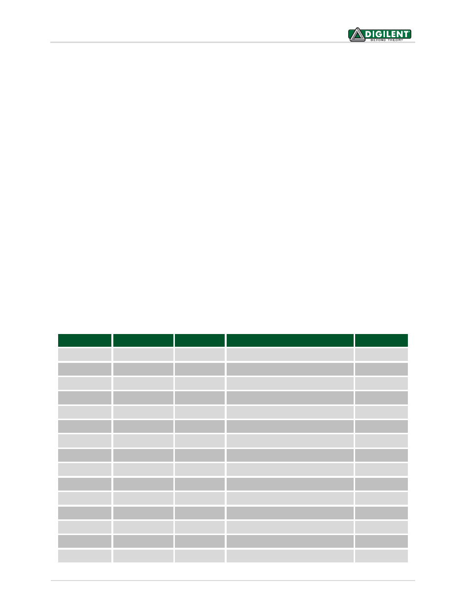
3.7.1 Pinout Table by Logical Pin Number
chipKIT Pin #
Connector Pin #
PIC32 Pin #
PIC32 Signal
Notes
0
J14-01
52
SDA1A/SDI1A/U1ARX/RF2
1
J14-03
53
SCL1A/SDO1A/U1ATX/RF8
2
J14-05
18
AERXD0/INT1/RE8
3
J14-07
72
SDO1/OC1/INT0/RD0
4
J14-09
74
SOSCO/T1CK/CN0/RC14
5
J14-11
76
OC2/RD1
6
J14-13
77
OC3/RD2
7
J14-15
19
AERXD1/INT2/RE9
8
J3-01
79
ETXD2/IC5/PMD12/RD12
9
J3-03
78
OC4/RD3
10
J3-05
81
OC5/PMWR/CN13/RD4
11
J3-07
9
T5CK/SDI1/RC4
12
J3-09
58
SCL2/RA2
13
J3-11
59
SDA2/RA3
14
J4-08
39
AC1TX/SCK3A/U3BTX/U3ARTS/RF13