12 on-board i/o, 13 pmod expansion connectors, On-board i/o – Digilent 6015-410-001P-KIT User Manual
Page 10: Pmod expansion connectors
NetFPGA-1G-CML™ Board Reference Manual
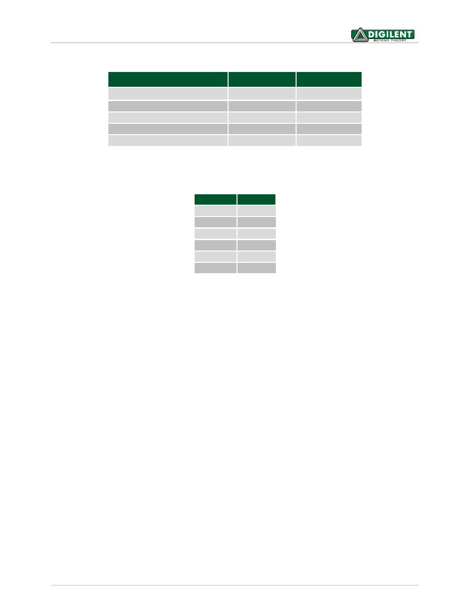
Component Name
PIC I
2
C Controller I
2
C 7-bit Address
AD5274 Digital Rheostat
I2C2
0101110
ADM1177 Hot Swap Controller
I2C2
1011011
ATSHA204 CryptoAuthentication I2C2
1100100
M41T62 Real-Time Clock
I2C2
1101000
24LC128 Serial EEPROM
I2C1
1010001
Table 3. PIC I
2
C Peripheral Address Map.
Flash Pin PIC Port
CS
RB10
SCLK
RB11
SI
RB12
SO
RB13
WP
RB14
HOLD
RB15
Table 4. PIC Flash Connections.
12 On-Board I/O
Built-in on-board I/O includes four LEDs and six buttons. Four of the buttons are general-purpose and two are set
aside for special functions. The red special function buttons are reserved for use as an on-chip reset (BTN4 - RESET)
to reset the design logic and a configuration reset (BTN5 – PROG) which initiates a new FPGA configuration
sequence like that which occurs at power-on. It is important to note that the buttons and LEDs are not all
constrained to the same IOSTANDARD on their associated ports, since they are connected to otherwise un-
allocated ports in different FPGA IO banks. Please refer to Appendix B for specific details regarding the button and
LED IO port constraints.
13 PMOD Expansion Connectors
The NetFPGA-1G has two 12-pin connectors to support I/O expansion via Digilent Pmods. Digilent manufactures
Pmod accessories that support a large variety of external interfaces that increase system flexibility. The Pmod
connectors are 2x6 right-angle 100-mil female connectors that work with the standard 2x6 headers available from
a variety of distributors. On the NetFPGA-1G, each 12-pin Pmod connector provides two 3.3V VCC supply
connections (pins 6 and 12), two Ground connections (pins 5 and 11), and eight logic signals (Fig. 2). The supply
pins can provide up to 1A of current to connected Pmod devices. The logic signals are not matched pairs. They are
routed without impedance control or delay matching. Note also that the connectors are not keyed, so care should
be taken to verify that any connected devices have Pin 1 aligned with Pin 1 on the connector. Pin1, VCC and GND
are clearly labeled on the PCB to help simplify proper connection.
Copyright Digilent, Inc. All rights reserved.
Other product and company names mentioned may be trademarks of their respective owners.
Page 10 of 26