Section 13, Parts replacement and precautions – Toshiba VT130G1 User Manual
Page 83
Attention! The text in this document has been recognized automatically. To view the original document, you can use the "Original mode".
Section 13
PARTS REPLACEMENT AND PRECAUTIONS
1.
Before replacing parts, check that power is not supplied to the inverter and the
main circuit capacitor is not charged (CHARGE lamp is not illuminated).
2.
Replacement of parts on the printed circuit board must be performed by trained
personnel. Please contact your dealer.
3.
Removing the printed circuit board
The printed circuit board is fastened with locking supports at four corners.
Remove the connectors on the circuit board, remove the locking support and then
remove the circuit board.
4.
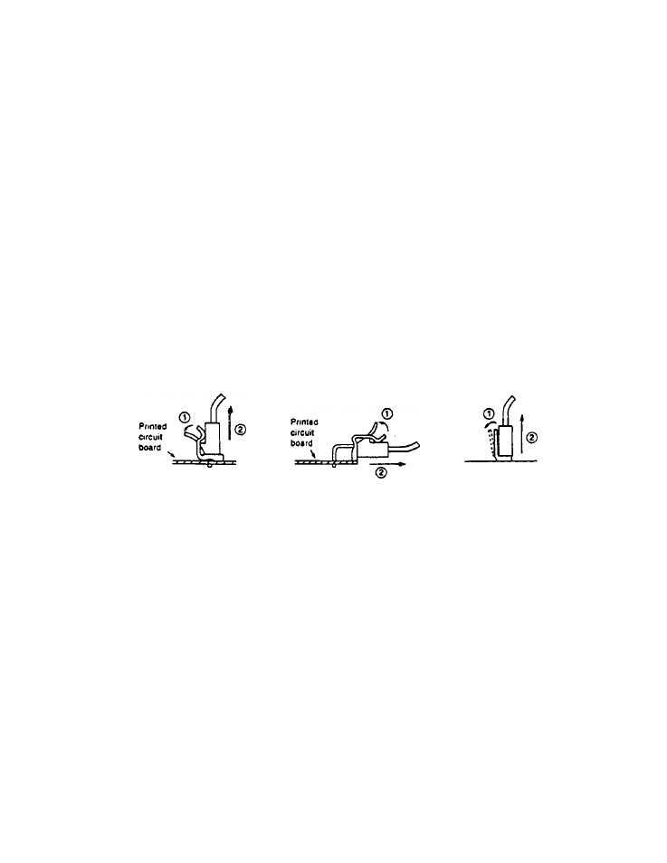
Removing connectors on the printed circuit board
Connectors are held with stoppers. Release the stopper and pull the connector
out carefully. Do not pull on the wire.
To plug the connector back in, push it in place to lock with the stopper.
Excessive force may cause damage. Hold the circuit board and push gently. Also
check the connector numbers and match the pins correctly.
In some models the connector on the base drive circuit board is difficult to get at.
In such case, remove the locking support and lift the circuit board so that the
connector can be grasped easily before removing.
5.
Replacing LED (7 segment indicator)
The LED indicator is plugged in a socket and can be easily replaced, but it
should not be removed unless necessary.