Toshiba VT130G1 User Manual
Page 28
Attention! The text in this document has been recognized automatically. To view the original document, you can use the "Original mode".
Section 6
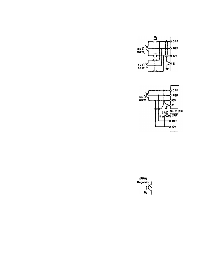
e) Switching between two or more variable resistors:
Two or more pots are set at
different frequencies and selected.
Use small current rated relay for
selection.. Disconnect the door
mounted pot from terminals CRF,
REF. and OV
f) Multiple inverter cascading with one setting device:
No 1
uak
Connect 3 K ohm w resistor
between CRF and OV terminal of
each slave unit. Disconnect the
door mounted pots on all units.
g) Multiple inverter cascading from one process signal:
4 to 20 mA input signal cannot be used. Use voltage (0 to 12v) signal only in
to all inverters. Turn door mounted speed pots into OFF position.
h) Selection of a variable resistor other than 3 kn for speed setting.
I"
(3 kn variable resistor is furnished
on inverter door)
-€4e-
Tv^
{
ref
I
I5v
CRF U 750 n
REF
OV
A 750n fixed resistor is to be used as R1 in the inverter unit so that the REF
value (Vf^Ep) is between 0 and 12V when regulator R2 is 3 kn and the voltage
(Vnep) is divided by R1 and R2.
If the resistance value of the regulator is to be changed, a compensation resistor
R3 is required.
26