Toshiba VT130G1 User Manual
Page 30
Attention! The text in this document has been recognized automatically. To view the original document, you can use the "Original mode".
20híl
b) Connection of remote ammeter (AM)
• Use DC 1 mA meter
• Use a 20 K ohms variable resistor for
the scale calibration.
• When using multiple meters, connect
meters with the same rating in series.
3.
Connection of run signals (forward, reverse)
a) When operating in one direction only
• Connect ST terminal directly to either F (forward) or R (reverse) terminal
with jumper.
• Connection must be made by customer between COM and ST on all 1.5 to
5.5KVA units and between STl and COM on all 8 to 33KVA units. Solid
jumper gives programmed STOP. MC interlock gives choice of coast or
programmed STOP.
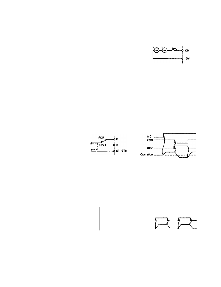
b) When operating in both directions
• Use FOR - REV switch as below. (1)
Section 6
Existing
$W Note: If both F (forward) and R (reverse) operating signals are connected at the same time. F (forward) command will override. (1) Use single pole, double throw, toggle switch rated for 24V DC. c) Acceleration and deceleration • Connect DRIVE switch and MC AUX as below. DRIVE MC ó F or R Ó ST (STl) MC DRIVE twitch ¿COM Speed MC: Input main contactor AUX. _J Inverter output frequency changes according to the preset acceleration and deceleration rates when unit is started or stopped. 28
twitch