Toshiba VT130G1 User Manual
Page 29
Attention! The text in this document has been recognized automatically. To view the original document, you can use the "Original mode".
Section 6
Obtain the compensation resistance R3 by substituting the value of the generator (R2)
in the following equation.
V
REF
15 V X Rj
75011 + Rj + R3
3 X Ra - 9000
12
= 12 V
(n)
where 5 kn > Ra > 3 kn
If a fixed resistor cannot be selected because R3 is not a round number, change R2
or use a variable resistor for R3.
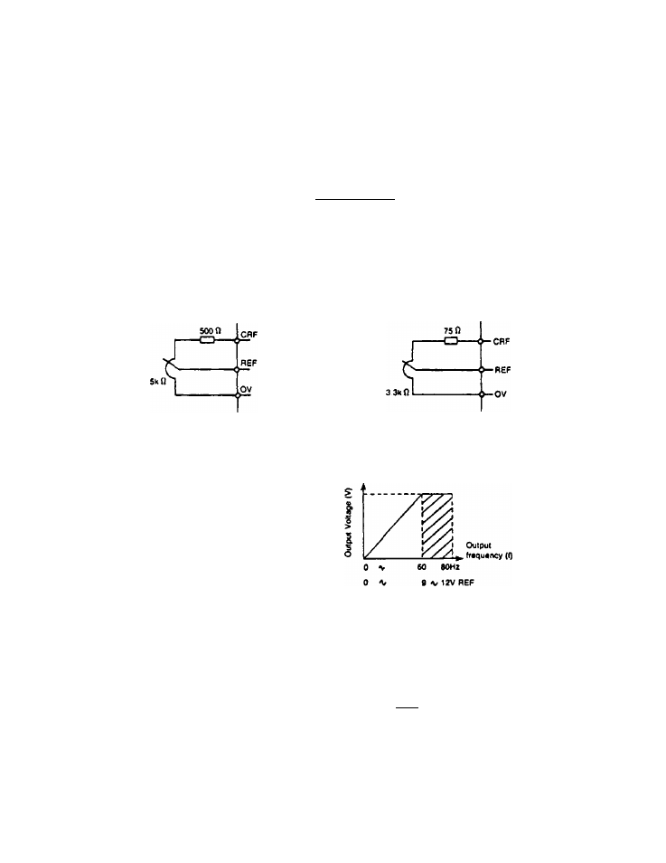
Selection examples:
variable resistor
variable resistor
Note: If the regulator is less than 3 k ohms, REF voltage becomes less than 0 to 12 V
and the maximum inverter output frequency decreases. Therefore R3 must be
greater than 3 k ohms. However, if V/F characteristic between 9 and 12 V (shaded
area) is not required, a regulator between 1.2 and 3 k ohms can be used.
Examples:
1) When 1.5 k ohms
Vqgp:
0 to 10 V variable
Output frequency: 0 to 66.7 Hz
2) When 2.5 k ohms
0 to 11.5 variable
Output frequency: 0 to 76.7 Hz
J2.
-H
2.
Connection of remote frequency meter and ammeter.
a) Connection of remote frequency meter (FM)
•
When the operating frequency is to be displayed
externally in addition to the digital display on the
unit, use DC1 mA meter.
• When using multiple meters, connect meters
with the same rating in series.
I~0^'
ov
FM
27