Sss 0h cno (aco (v-es) v (v-oo – Toshiba VT130G1 User Manual
Page 26
Attention! The text in this document has been recognized automatically. To view the original document, you can use the "Original mode".
Section 5
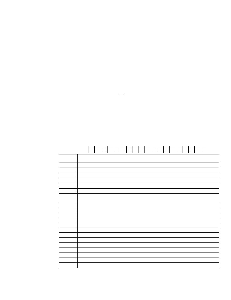
Figure 3-2 shows location of terminals, adjusting resistors, and FREQUENCY/FAULT
display on the Printed Circuit Board.
FIGURE 5*2
•lA Otl'«
fRIKTES CJffCUIT mus
OMRCC
OUIN CIRUIT
OMRCE IWICATOO
KAIH CONTROL
HUNTED CIRCUIT BOARD
(CWTROL VOLTAGE
OCCX
TEAUNALS)
C T i r
I
BASE ORIVE SIOUL
OCCX TEAUNALS)
CN U
z £ 1C ^
(BASIC OUTPUT
FREOUEHCT
SELECT JIMCR}
J3
-^1
90 HZ BO KZ
auTPUT fw-
ocxa RATIO
SELECT JUrCR}
izE
CT2
L±
CN 13
J5
11
11
If 2f 4f
I OF
90VER OISOiARCE
STSTEX SELEa
JUNPOU
(FREBJEXa t
fallt
OISPUY)
FREDUEXa/FAULT
(ADJUSTING RESISTORS)
1№ 2RH 3RH
4RH
JB
RESET
@
(FAULT RESET
BUTTOO
LI
t t
I III i
ulu
J13
W
XI X6
SSS 0H
cno (Aco (v-es) V (v-oo
SRH
6RH 7RH BRK 9RH lORN
0 SSSSS
(AC-TC FEEDBACK
SYSTEM SELECT
JUMPER)
(1^ REF (1-00 (ACO 0X0 OU QJJ
ARN1-B«S Qj TB
fLC FL8 FLA
¿L
OH RST ST
R
r
FM CH OV RCr CRT INF
T(X
JH
p
Terminal
Symbol
Terminal Function
fLC
Signal Common
FLB
'‘Open" Output iS obtained between FLB and F
l
C during inverter fault
FLA
"Closed" Output is obtained between FLA and FLC during inverter fault
P24V
+ 24 volts out
OH
Overtemperature contact input. OH incication when connected to +24 V (normally "Open" contact)
RST
Fault reset input Reset when connected to COM (Normally "open" contact)
ST
Start preparation/commar>d input: start preparation complete when ST connected to COM.
then start command complete when F or R is selected
R
Reverse operation input. Reverse operation when connected to ST
f
Forward operation input. Forward operation when connected to ST
COM
Signal common
FM
Remote frequency meter (1 mA mete* between FM and OV)
CM
Remote ammeter (i mA meter between CM and OV with 20 K calibration rheostat in series)
OV
Signal common
REF
External frequency reference input (0 • 12 VOC)
CRF
Power supply output to external frequency setting device
IRF
Current loop input (4 • 20 mA between IRF and OV)
TGP/FI
TG feedback signal (TOP • TON) (op'ion)
TGN/N
Pressure convener output (Ft - N) (option) ^ ■
P
Pressure convener power supply (opiion)
123
Pressure convener set point input (option)
24