Toshiba VT130G1 User Manual
Page 25
Attention! The text in this document has been recognized automatically. To view the original document, you can use the "Original mode".
Jumper Connections
Jumpers are connected to specification at the factory and should not be changed unless
necessary. The locations of jumpers are shown on Figure
5^2, page 24.
The function of each jumper is as follows.
Section 5
No.
Symbol on
Circuit Board
Function
Connection
at Shipment
J2
Ш.
If 2f 4f
Ratio of output frequency can be changed.
2f...Output frequency is doubled.
4f...Output frequency is quadrupled.
If
J3
16 6 ¿1
SQ HZ 60 HZ
Output frequency can be switched between
50 H
2
and 60 Hz according to jumper
selection.
60 Hz
JS
J5
о 0
Disconnect when adding regenerative
discharge resistor unit (option).
Connected
l
O о
Jt3
X6 XI
Acceleration/Deceieration time can be changed
XI — 1 -i- about 20 sec
X6 6 ~ about 120 sec Available in some models
XI
Note 1: Do not touch jumpers that are not described above.
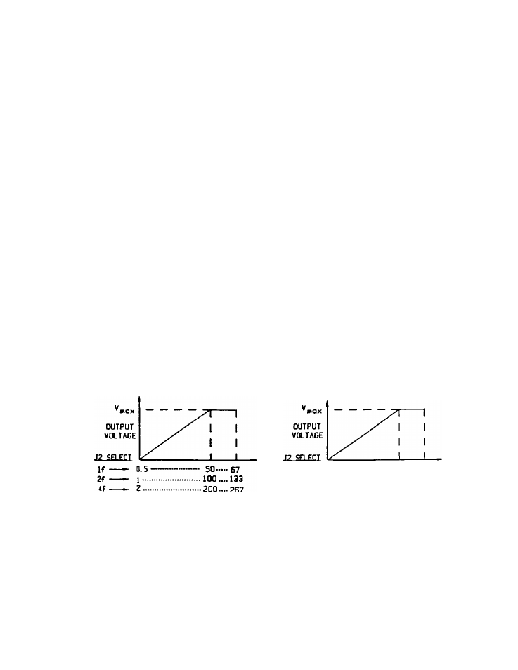
Note 2: J2 and J3 jumpers —
The V/F characteristic is as follows when J2 and J3 jumpers are switched,
a) When J3 is set to 50 Hz
b) When J3 is set to 60 Hz
(XITPUT FREQUENa (HZ)
If
2f
4f
0.S
60.......80
1......................... 120 »»160
2......................... 240»» 320
OUTPUT FREOUEtO (HZ)
23