Toshiba VT130G1 User Manual
Page 10
Attention! The text in this document has been recognized automatically. To view the original document, you can use the "Original mode".
Section 3
Output waveforms are illustrated in Figure
Output
u-v
v-w
w • u
FIGURE 3-5
Proper 120^ phase shift between output leads stays constant over the entire frequency
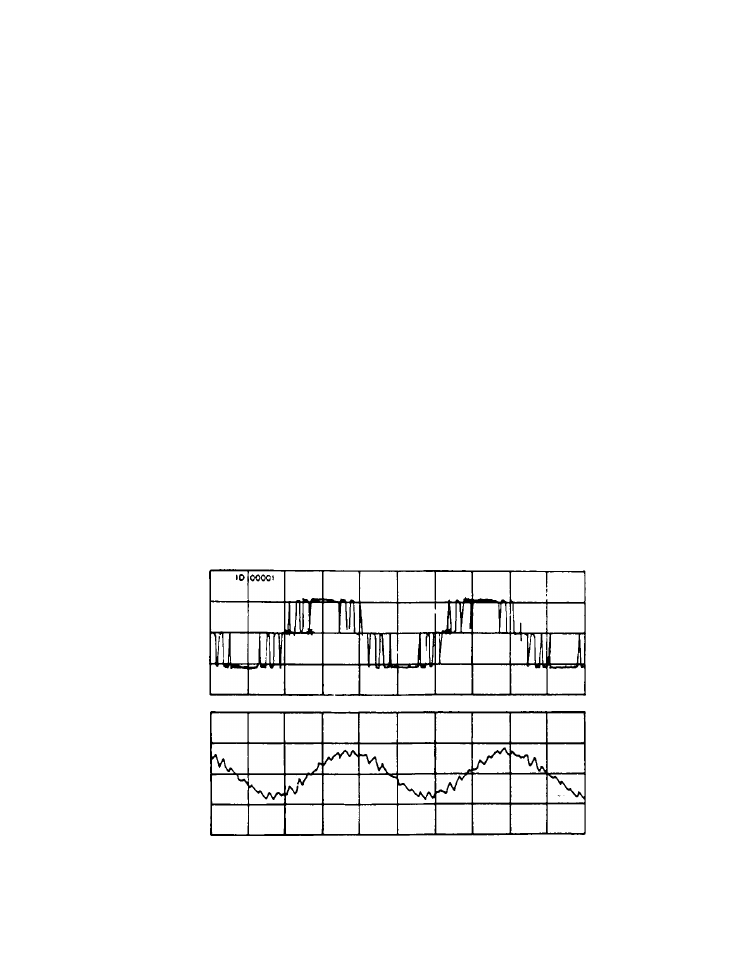
range. Typical motor voltage and current at 60 hertz (full load) is shown on Figure 3*6.
Note that although the voltage is in pulses, the current waveform is near sinusoidal.
Voltage s leading current, typical in induction motors.
OUTPUT VOLTAGE AND CURRENT
VOLTS
CURRENT
FIGURE 3*6
See also other documents in the category Toshiba Tools:
- Power Inverter (15 pages)
- 1800 (6 pages)
- TOSVERT VF-S11 (68 pages)
- Uninterruptible Power System G9000 (104 pages)
- Density (Consistency) Meter LQ500 (9 pages)
- MBSB80-225-43 (1 page)
- TOSNIC-7000S (53 pages)
- 1600EP Series (3 pages)
- 1500 (32 pages)
- TOSVERT VF-FS1 Series (16 pages)
- 4200FA XT1 (1 page)
- G3 Plus Pack (4 pages)
- Tosvert VF-A5 (149 pages)
- 1600 Series (3 pages)
- G9000 (100 pages)
- TEC EO1-33030 (54 pages)
- 1000 Series (2 pages)
- 1500 Plus (31 pages)
- G8000MM (6 pages)
- 4200FA Series (2 pages)
- VF-PS1 (10 pages)
- GX7 Series (6 pages)
- 4200FA XT (1 page)
- RMTI-EMD-HT (2 pages)
- W7 Series (6 pages)
- HX7 (6 pages)
- PDP002Z (18 pages)
- RELIABILITY IN MOTION 1700 (39 pages)
- 1700 Series (2 pages)
- G3 TOSVERT-130 (62 pages)
- B-852-TS12-QP (55 pages)
- 1000 (4 pages)
- E3 (7 pages)
- Adjustable Speed Drive H3 (122 pages)
- 55611-001 (2 pages)
- Black Gold Series (2 pages)
- Dura-Bull TX (6 pages)
- Current Relay RC803A-HP1 (19 pages)
- 1800 SERIES (2 pages)
- Isolated-Redundant UPS System (2 pages)
- Tosvert VF-AS1 (312 pages)
- RELIABILITY IN MOTION 1000 (54 pages)
- REMOTE-D (2 pages)
- 15-80KVA (2 pages)