Introduction – AERCO CXT-E Retrofit Kit User Manual
Page 68
ECS and CXT-E Retrofit Instructions Kit # 27004-TAB
Technical Instruction Document
TID-0141_0A
12/30/2014
AERCO International, Inc. • 100 Oritani Dr. • Blauvelt, New York 10913 • Phone: 800-526-0288 Page 68 of 76
INTRODUCTION
The information included in this Appendix lists optional items which may vary, depending on:
• Type of Water Heater being retrofitted
• Required Water Heater flow rate
• Type of Control Valve Actuator previously installed
• Control Valve size
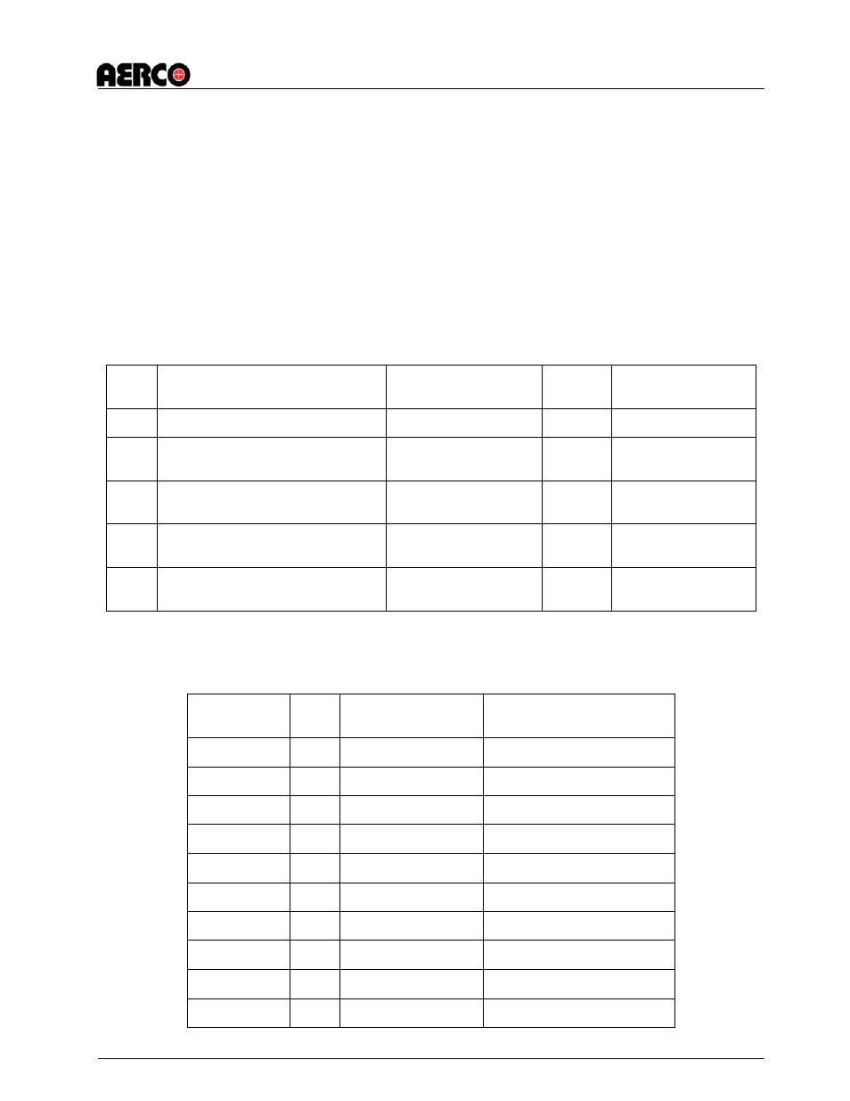
Table B-1 and the Tables/Appendices referenced therein, list the applicable items included in the
Retrofit Kit for the specific Water Heater being retrofitted.
TABLE B-1. ECS RETROFIT KIT OPTIONAL ITEMS
ITEM
DESCRIPTION
LOCATION ON UNIT
QTY.
REFERENCE
TABLE/APPENDIX
1
Orifice Disc
Cold Water Inlet
1
Table B-2
2
Compound Pressure Gauge
(Steam-to Water Units ONLY)
Steam Inlet to Heater
1
Table B-3
3
Valve Flange Gaskets
(2.50” to 4.00” Valves ONLY)
Control Valve Inlet &
Outlet Flanges
2
Table B-4
4
Pneumatic or Electro-Hydraulic
Actuator Replacement Kit
Control Valve
1
Appendix C
5
Self-Contained Actuator
Replacement Kit
Control Valve
1
Appendix D
TABLE B-2. ORIFICE DISC OPTIONS (Table B-1, Item 1)
AERCO
PART NO.
QTY
WATER HEATER
FLOW RATE (GPM)
APPLICABLE UNITS
49032-1
1
0 – 45
B-Plus, B-Plus II, E-Plus
49032-2
1
0 – 70
B-Plus, B-Plus II, E-Plus
49032-3
1
0 – 125
B-Plus, B-Plus II, E-Plus
49032-4
1
> 125
B-Plus, B-Plus II, E-Plus
49032-5
1
0 – 45
A-Plus, WWDW-24
49032-6
1
0 – 70
A-Plus
49032-7
1
0 – 100
WWDW-45, WWDW-68
49032-8
1
0 – 45
WWDW-45, WWDW-68
49032-9
1
0 – 125
WWDW-45, WWDW-68
49032-10
1
> 125
WWDW-68