2 water-to-water double-wall water heaters – AERCO CXT-E Retrofit Kit User Manual
Page 46
ECS and CXT-E Retrofit Instructions Kit # 27004-TAB
Technical Instruction Document
TID-0141_0A
12/30/2014
AERCO International, Inc. • 100 Oritani Dr. • Blauvelt, New York 10913 • Phone: 800-526-0288 Page 46 of 76
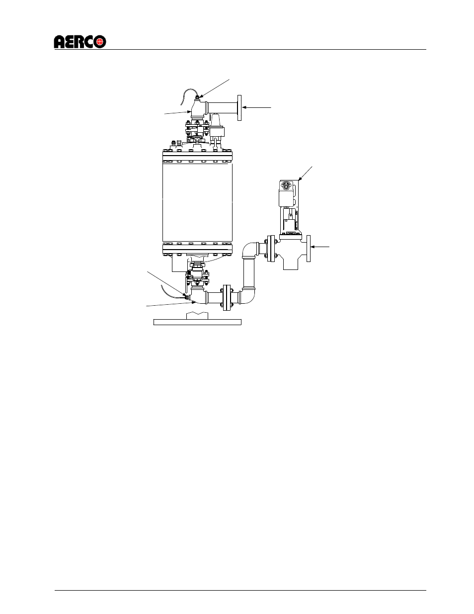
BOILER WATER
OUTLET
BOILER WATER
INLET
CXT-E
CONTROL
VALVE
BOILER WATER
INLET SENSOR
LOCATION
BOILER WATER
OUTLET SENSOR
LOCATION
VALVE SPOOL
PIECE ASSEMBLY
VALVE SPOOL
PIECE ASSEMBLY
Figure 4-9. E-Plus Boiler Water Inlet and Outlet Temperature Sensor Locations
4.4.2 Water-to-Water Double-Wall Water Heaters
The sensor installation locations for a Water-to-Water Model WWDW-24 differ slightly from the
locations used for WWDW-45 and DW-68 Models as shown in Figure 4-10. DW-45 and WWDW-
68 Sensors are mounted on the Boiler Water Inlet and Outlet Flanges. However, since these
flanges do not exist for the WWDW-24, the Sensors are mounted on the bottom of the Boiler
Water Inlet and Outlet as shown in Figure 4-10. Install the Boiler Water Inlet and Outlet Sensors
as follows for the Model being retrofitted:
1. Check to ensure that the capillary tubes and compression fittings have been removed from
the Boiler Inlet and Outlet Flanges shown in Figure 4-10. If they have not been previously
remove, disconnect and remove these items at this time.
2. For WWDW-45 and WWDW-68 Models, install the Boiler Water Inlet Temperature Sensor in
the tapped opening in the Boiler Water Inlet Flange shown in Figure 4-10. For a WWDW-24
Model, install the Sensor in the tapped hole at the bottom of the Boiler Water Inlet as
shown.
3. For WWDW-45 and WWDW-68 Models, install the Boiler Water Outlet Temperature Sensor
in the tapped opening in the Boiler Water Outlet Flange shown in Figure 4-10. . For a
WWDW-24 Model, install the Sensor in the tapped hole at the bottom of the Boiler Water
Inlet as shown.
4. The electrical connector plugs on the Inlet and Outlet Boiler Water Temperature Sensors
will be connected after the ECS Control Box is installed (section 4.5).