Carrier 48AJ User Manual
Page 96
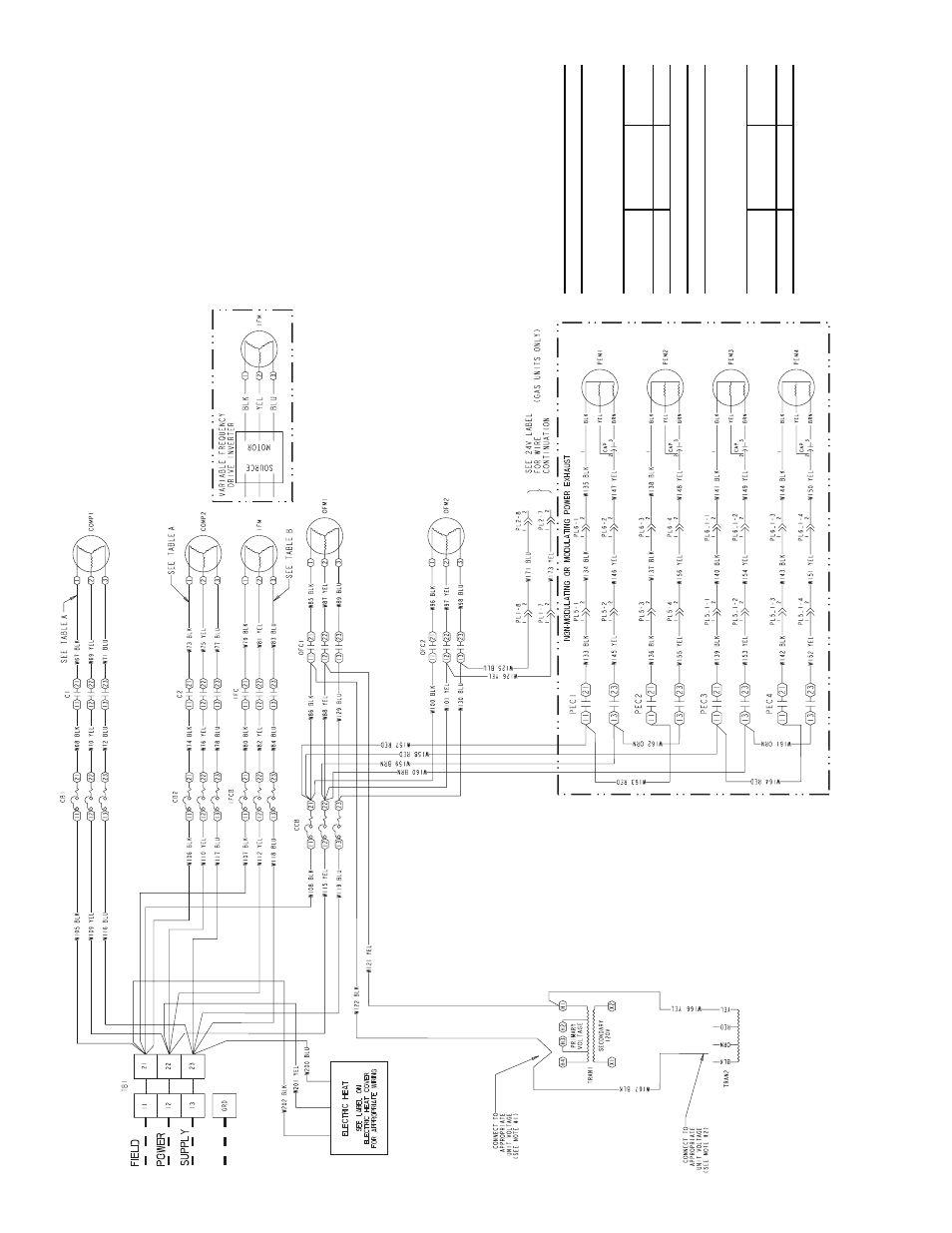
96
F
ig.
77
— T
y
pi
ca
l
Pow
e
r
Sche
mati
c
4
8
EJ,
E
K,EW,
E
Y0
24
-03
4
; 2
0
8
/2
30-
3-
60
a
nd
46
0-3
-6
0
N
O
TES:
1.
C
onnect TR
A
N
1 to
H4 f
o
r 460
v units
.
Connect to
H
3
f
o
r 230 v
. If 208/230 v units are r
un wit
h
a
20
8-v po
w
e
r supply
, connect to H2.
2.
C
onnect TR
A
N
2 to b
lac
k lead
fo
r 4
60 v units
.
C
onnect
to or
ange
lead f
o
r 230 v units
.
If 208/230
v un
its are r
un w
ith
a 208
-v po
w
e
r supply
, con-
ne
ct to red lead.
3.
C
ircuit break
er m
u
st tr
ip
amps
are e
qual
to or
less than 15
6% FL
A
f
o
r CB1 and CB2. All othe
rs
are 140%
.
4.
If an
y
of the
or
iginal
wire fur
n
ished m
u
st
be
repla
c
ed,
it m
u
st b
e
repla
c
ed
with
T
y
pe
90 C
wire
or its equiv
a
lent.
5.
C
o
mpresso
rs and/or f
a
n
motors
are
ther
mally
protected.
6.
T
h
ree phase motors are
protected against pr
i-
mar
y
single
phasing conditio
n
s
.
T
ABL
E 1A
Th
e f
o
llo
win
g
co
mp
re
ssor
s
h
a
ve tw
o
parallel wires run
fr
om T
B
1 t
o
th
e
co
mp
ressor
s
.
Com
p
ress
or
Model
Vo
lt
a
g
e
Wire
Qu
ant
ity
06D-537
208/23
0-3-6
0
2
T
ABL
E 2B
T
h
e f
o
llo
win
g
f
a
n m
o
to
rs
ha
ve tw
o
parall
el wires
ru
n f
rom
T
B
1 to
th
e fan
mo
tor
s
.
In
do
or
Motor
Vo
lt
a
g
e
Wire
Qu
ant
ity
20 H
P
208/23
0-3-6
0
2