Carrier 48AJ User Manual
Page 25
25
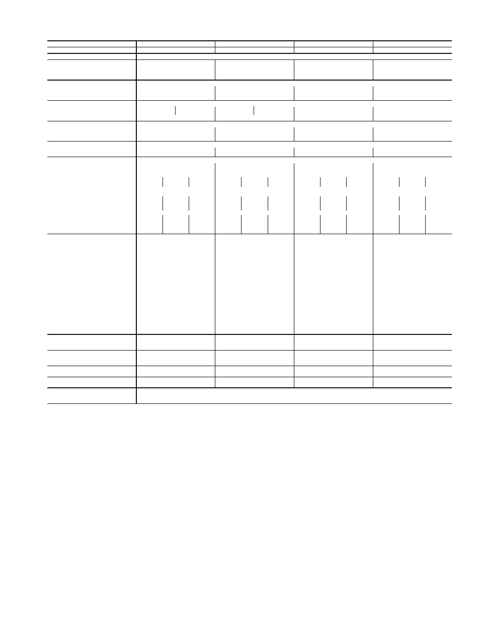
Table 1B — Physical Data — 48EJ,EK,EW,EY Units (cont)
*Circuit 1 uses the left condenser coil. Circuit 2 the right. All units have intertwined evaporator coils.
†Motor and drive shown will deliver approximately 2.5 in. wg net external static pressure. For more information see Table 3.
**Rollout switch is manual reset.
NOTE: High heat is for 48EJ,EW.
UNIT 48EJ,EK,EW,EY
054D/E
058D/E
064D/E
068D/E
NOMINAL CAPACITY (tons)
50
55
60
65
OPERATING WEIGHT (lb)
For Operating Weights see Table 2.
COMPRESSOR
Quantity...Type (Ckt 1, Ckt 2)
1...06EA265, 1...06EA250
1...06EA275, 1...06EA250
1...06EA275, 1...06EA265
2...06EA275
Number of Refrigerant Circuits
2
2
2
2
Oil (oz) (Ckt 1, Ckt 2)
304, 224
304, 224
304, 304
304, 304
REFRIGERANT TYPE
R-22
Operating Charge (lb-oz)
Circuit 1*
50-11
57-0
68-0
81-0
Circuit 2
46-8
48-6
68-0
73-0
CONDENSER COIL
Cross-Hatched
3
/
8
″-in. Copper Tubes, Aluminum Lanced, Aluminum Pre-Coated, or Copper Plate Fins
Quantity
1 1
1 1
2
2
Rows...Fins/in.
3...15 2...15
3...15 2...15
3...15
4...15
Total Face Area (sq ft)
66.6
100.0
100
100
CONDENSER FAN
Propeller Type
Nominal Cfm
30,000
43,900
43,900
43,900
Quantity...Diameter (in.)
4...30
6...30
6...30
6...30
Motor Hp (1075 Rpm)
1
1
1
1
EVAPORATOR COIL
Cross-Hatched
1
/
2
″-in. Copper Tubes, Aluminum Plate Fins, Intertwined Circuits
Rows...Fins/in.
4...17
4...17
4...17
4...17
Total Face Area (sq ft)
45.0
45.0
48.1
48.1
EVAPORATOR FAN
Centrifugal Type
Quantity...Size (in.)
3...20x15
3...20x15
3...20x15
3...20x15
Type Drive
Belt
Belt
Belt
Belt
Nominal Cfm
20,000
22,000
24,000
26,000
Motor Hp
15
20†
25
20
25†
30
25
30†
40
25
30†
40
Motor Frame Size
S254T
S256T
S284T
S256T
S284T
S286T
S284T
S286T
S324T
S284T
S286T
S324T
Motor Bearing Type
Ball
Ball
Ball
Ball
Maximum Allowable Rpm
1200
1200
1200
1200
Motor Pulley Pitch Diameter
4.7
6.1
8.1
5.9
6.7
7.5
5.3
8.1
9.4
6.7
5.9
9.4
Nominal Motor Shaft Diameter (in.)
1
5
/
8
1
5
/
8
1
7
/
8
1
5
/
8
1
7
/
8
1
7
/
8
1
7
/
8
1
7
/
8
2
1
/
8
1
7
/
8
1
7
/
8
2
1
/
8
Fan Pulley Pitch Diameter (in.)
11.1
11.1
12.5
11.1
11.1
11.1
9.1
12.5
13.6
12.5
9.5
13.6
Nominal Fan Shaft Diameter (in.)
1
15
/
16
1
15
/
16
1
15
/
16
1
15
/
16
Belt, Quantity...Type
2...5VX550 2...5VX570 2...5VX630 2...5VX570 2...5VX590 2...5VX590 3...5VX530 2...5VX630 2...5VX650 2...5VX610 3...5VX550 2...5VX650
Length (in.)
55
57
63
57
59
59
53
63
65
61
55
59
Pulley Center Line Distance (in.)
15.2-17.5
15.2-17.5
14.7-17.2
15.2-17.5
14.7-17.2
14.7-17.2
14.7-17.2
14.7-17.2
14.2-17.0
14.7-17.2
14.7-17.2
14.3-17.0
Factory Speed Setting (rpm)
741
962
1134
930
1056
1182
1019
1134
1214
938
1087
1214
FURNACE SECTION
Rollout Switch Cutout Temp (F)**
225
225
225
225
Burner Orifice Diameter
(in. ...drill size)
Natural Gas Std
.120...31
.120...31
.120...31
.120...31
Liquid Propane Alt
.096...41
.096...41
.096...41
.096...41
Thermostat Heat Anticipator
Setting (amps)
Stage 1
0.1
0.1
0.1
0.1
Stage 2
0.1
0.1
0.1
0.1
Gas Input (Btuh)
Stage 1
441,000/ 873,000
441,000/ 873,000
441,000/ 873,000
441,000/ 873,000
Stage 2
662,400/1,164,000
662,400/1,164,000
662,400/1,164,000
662,400/1,164,000
Efficiency (Steady State) (%)
82
82
82
82
Temperature Rise Range
10-40/30-60
10-40/30-60
10-40/30-60
10-40/30-60
Gas Pressure to Unit Range (in. wg)
5 - 13.5
5 - 13.5
5 - 13.5
5 - 13.5
Manifold Pressure (in. wg)
Natural Gas
Std
3.3
3.3
3.3
3.3
Liquid Propane
Alt
3.3
3.3
3.3
3.3
Gas Valve Quantity
3
3
3
3
Field Gas Connection Size
(in.-FPT)
2.5
2.5
2.5
2.5
HIGH-PRESSURE SWITCH (psig)
Cutout
426
426
426
426
Reset (Auto.)
320
320
320
320
LOW-PRESSURE SWITCH (psig)
Cutout
7
7
7
7
Reset (Auto.)
22
22
22
22
RETURN-AIR FILTERS (W x H x T)
Quantity...Size (in.)
16...20 x 24 x 2
16...20 x 24 x 2
16...20 x 24 x 2
16...20 x 24 x 2
OUTDOOR-AIR FILTERS
12...16 x 25
12...16 x 25
12...16 x 25
12...16 x 25
Quantity...Size (in.)
6...20 x 25
6...20 x 25
6...20 x 25
6...20 x 25
POWER EXHAUST
Direct Drive, 3-Speed, Single-Phase Motor (Factory-Wired for High Speed) and Forward Curved Fan
Motor, Quantity...Hp
6...1
Fan, Diameter...Width (in.)
11...10