11 auxiliary relay contacts, 12 flue gas vent installation, Installation – AERCO BMK 3.0 LN Dual-Fuel Series Gas Fired Low NOx Boiler System User Manual
Page 21
INSTALLATION
2-11
depressed. The fault relay connections are
shown in Figure 2-11.
2.10.12
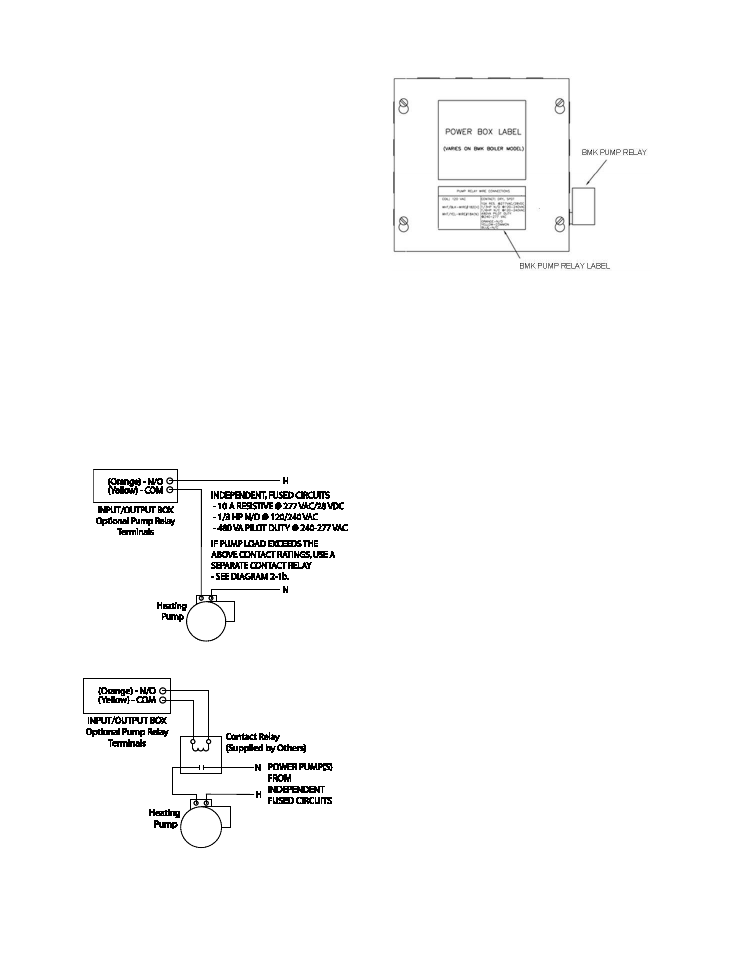
BENCHMARK PUMP RELAY
OPTION
An optional Benchmark pump relay allows the
user to turn a pump on/off and open/close a
motorized valve as the boiler cycles on and off
on demand. The Pump Delay Timer feature
allows the user to keep the pump running and
keep the motorized valve open for up to 30
minutes after the boiler has shut down and the
demand is satisfied.
The Benchmark pump relay (SPDT) contact is
rated for:
•
10 A Resistive @ 277 VAC/28 VDC
•
1/3 HP N/O @ 120/240 VAC
•
1/6 HP N/C @ 120/240 VAC
•
480 VA Pilot Duty @ 240-277 VAC
If pump/valve load exceeds the above contact
ratings, use a separate contact relay.
See Diagrams 2-1a and 2-1b.
To identify if the boiler is equipped with the BMK
Pump Relay Option (part no. 69102), look for the
label and relay as shown in Figure 2-12.
Diagram 2-1a: Schematic – System Pump
Start using Boiler Pump Relay
Diagram 2-1b: Schematic – System Pump
Start using a Separate Contact Relay
Figure 2-12: Identifying the Presence of BMK
Pump Relay Option 69102
2.11 AUXILIARY RELAY CONTACTS
Each Boiler is equipped with a single pole
double throw (SPDT) relay that is energized
when there is a demand for heat and de-
energized after the demand for heat is satisfied.
The relay is provided for the control of auxiliary
equipment, such as pumps and louvers, or can
be used as a Boiler status indictor (firing or not
firing). Its contacts are rated for 120 VAC @ 5
amps. Refer to Figure 2-11 to locate the AUX
RELAY terminals for wiring connections.
2.12 FLUE GAS VENT INSTALLATION
The minimum allowable vent diameter for a
single Benchmark 3.0 Dual-Fuel Boiler is 8
inches.
The AERCO Benchmark Venting and
Combustion Air Guide, GF-2050, must be
consulted before any flue gas vent or inlet air
venting is designed or installed. U/L listed,
positive pressure, watertight vent materials as
specified in AERCO’s GF-2050, must be used
for safety and code compliance. Since the unit is
capable of discharging low temperature exhaust
gases, horizontal sections of the flue vent
system must be pitched back to the unit a
minimum of 1/4 inch per foot to avoid
condensate pooling and allow for proper
drainage.
The combined pressure drop of vent and
combustion air systems must not exceed 140
equivalent feet of 8 inch ducting. Fittings as well
as pipe lengths must be calculated as part of the
equivalent length.
For a natural draft installation the draft must not
exceed ±0.25 inch W.C. These factors must be
planned into the vent installation. If the
maximum allowable equivalent lengths of piping
are exceeded, the unit will not operate properly
or reliably.