2 setting the unit, Installation – AERCO BMK 3.0 LN Dual-Fuel Series Gas Fired Low NOx Boiler System User Manual
Page 12
INSTALLATION
2-2
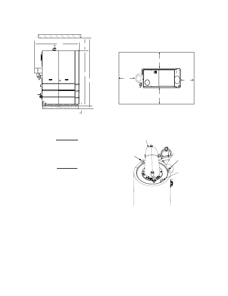
43"
24"
24"
24"
4" HIGH PAD
REAR
FRONT
77"
18"
101"
79"
Figure 2-1 Benchmark 3.0 Dual Fuel Boiler Clearances
WARNING
KEEP THE UNIT AREA CLEAR AND
FREE FROM ALL COMBUSTIBLE
MATERIALS AND FLAMMABLE
VAPORS OR LIQUIDS
.
CAUTION
While packaged in the shipping
container, the boiler must be moved
by pallet jack or forklift from the
FRONT ONLY.
2.4.2 Setting the Unit
The unit must be installed on a 4 inch to 6 inch
housekeeping pad to ensure proper condensate
drainage. If anchoring the unit, refer to the
dimensional drawings in Appendix F for anchor
locations. A total of 3 lifting tabs are provided at
the top of the primary heat exchanger as shown
in Figure 2-2. However, USE ONLY TABS 1
AND 2 SHOWN IN FIGURE 2-2 TO MOVE THE
ENTIRE UNIT. Tabs 1 and 3 are used only
when removing or replacing the unit’s primary
heat exchanger. Remove the front top panel
from the unit to provide access to the lifting tabs.
Remove the four (4) lag screws securing the unit
to the shipping skid. Lift the unit off the shipping
skid and position it on the 4 inch to 6 inch
housekeeping concrete pad (required) in the
desired location.
PRIMARY HEAT
EXCHANGER
LIFTING
TAB 2
LIFTING
TAB 1
BURNER
ASSEMBLY
LIFTING
TAB 3
Figure 2-2
Lifting Lug Locations
In multiple unit installations, it is important to
plan the position of each unit in advance.
Sufficient space for piping connections and
future service/maintenance requirements must
also be taken into consideration. All piping must
include ample provisions for expansion
.
If installing a Combination Control Panel (CCP)
system, it is important to identify the
Combination Mode Boilers in advance and place
them in the proper physical location. Refer to
Chapter 5 for information on Combination Mode
Boilers.