9 modes of operation and field control wiring, 1 constant setpoint mode, Benchmark 2.0ln dual-fuel low nox boiler – AERCO BMK 2.0 LN Dual Fuel Serial G-11-2402 and UP User Manual
Page 19: Gf-127
CHAPTER 2: INSTALLATION
PR2: 04/22/13 Page 19 of 160
Benchmark 2.0LN Dual-Fuel Low NOx Boiler
Operation and Maintenance Manual
OMM-0052_0E
GF-127
AERCO International, Inc. • 100 Oritani Dr. • Blauvelt, NY 10913 • Ph: 800-526-0288
GND
NEU
L1
120 VAC, 1 PHASE
Figure 2-8: AC Terminal Block Configurations
2.9 MODES OF OPERATION AND FIELD CONTROL WIRING
The Benchmark 2.0 Boiler is available in several different modes of operation. While each unit
is factory configured and wired for its intended mode, some additional field wiring may be
required to complete the installation. This wiring is typically connected to the Input/Output (I/O)
Box located on the lower portion of the unit front panel (Figure 2-9) behind the removable front
door.
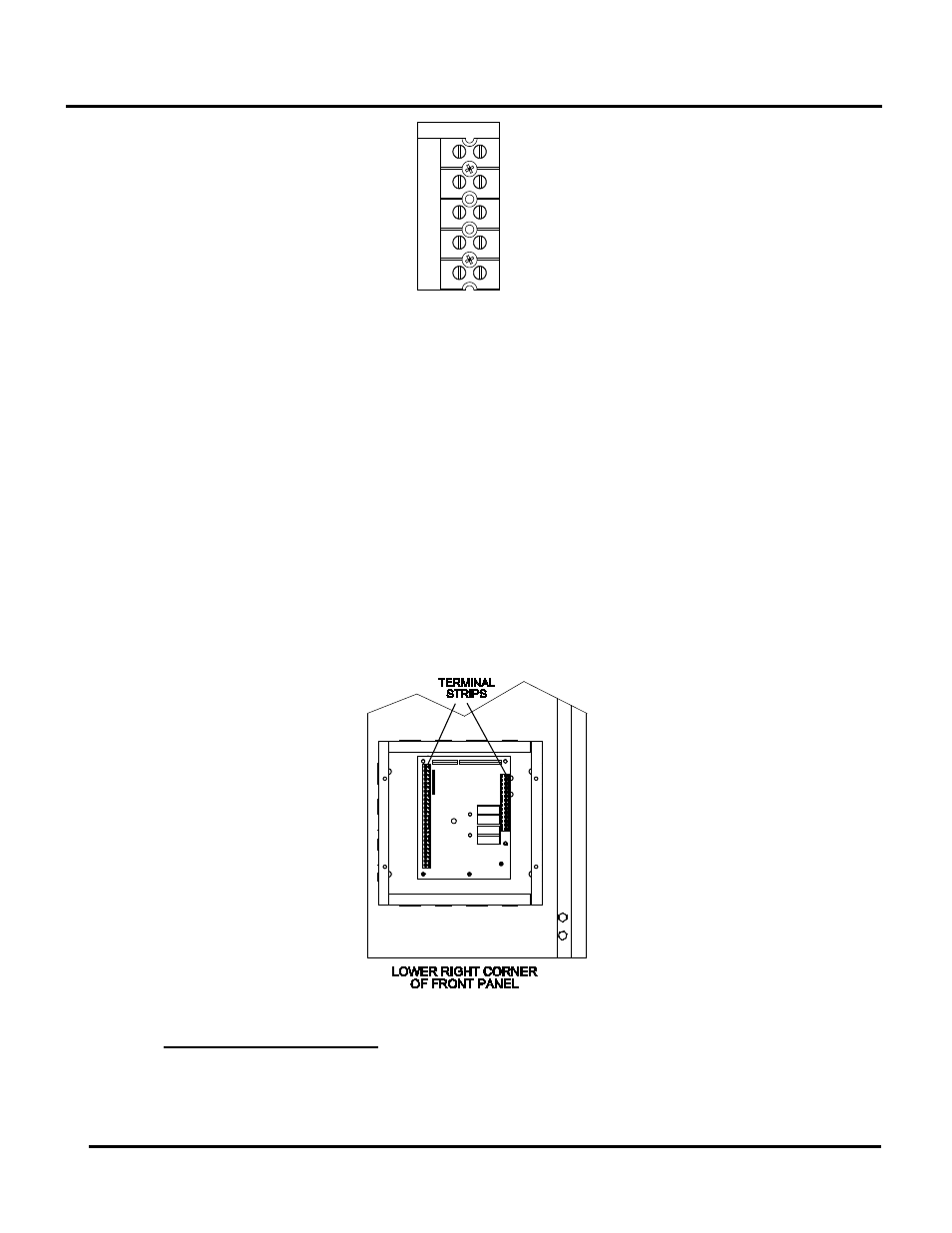
To access the I/O Box terminal strips shown in Figure 2-9, loosen the four cover screws and
remove the cover. All field wiring is installed from the rear of the panel by routing the wires
through one of the four bushings provided.
Refer to the wiring diagram provided on the cover of the I/O Box when making all wiring
connections.
Brief descriptions of each mode of operation, and their wiring requirements, are provided in the
following paragraphs. Additional information concerning field wiring is provided in paragraphs
2.10.1 through 2.10.13. Refer to Chapter 5 for detailed information on the available modes of
operation.
Figure 2-9: Input/Output (I/O) Box Location
Constant Setpoint Mode
2.9.1
The Constant Setpoint Mode is used when it is desired to have a fixed setpoint that does not
deviate. No wiring connections, other than AC electrical power connections, are required for
this mode. However, if desired, fault monitoring or enable/disable interlock wiring can be
utilized (see paragraphs 2.10.11.1 and 2.10.11.2).