7 condensate trap, Maintenance, Figure 7-5 burner assembly exploded view – AERCO BMK 2.0 LN Nat. Gas June 2010 User Manual
Page 61: Figure 7-6 condensate trap
MAINTENANCE
BLOWER
PROOF
SWITCH
BLOCKED
INLET
SWITCH
AIR/FUEL
VAVLE
STAGED
IGNITION
ASSEMBLY
FLAME
DETECTOR
BURNER
PLATE
HEX NUTS &
WASHERS (6)
BLOWER
GASKET
IGNITOR-
INJECTOR
BURNER
BLOWER
BURNER
GASKET
BURNER
GASKET
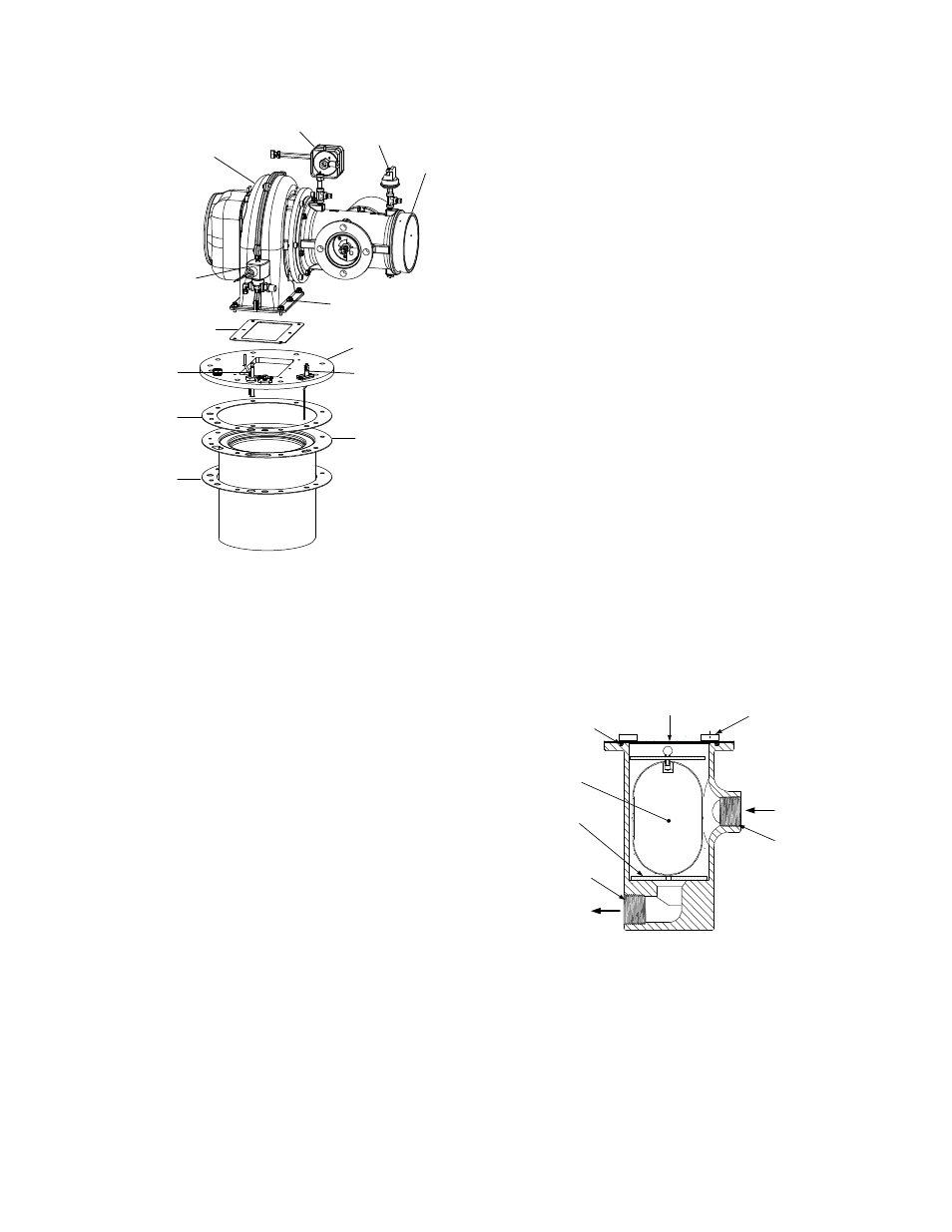
Figure 7-5
Burner Assembly Exploded View
15. Remove the blower and air/fuel valve from
the burner plate by lifting straight up. Also,
remove the blower gasket which will be
replaced with a new gasket.
16. Remove the eight (8) 3/8-16 nuts from the
burner flange (Figure 7-4) using a 9/16”
wrench.
NOTE
The burner assembly is heavy, weighing
approximately 30 pounds.
17. Remove the burner assembly from burner
flange by pulling straight up.
18. Remove and replace the two (2) burner
gaskets.
NOTE
During reassembly, apply high-tempera-
ture, anti-seize lubricant to the threads of
the ignitor-injector and grounding screw.
Also, ensure that the ignitor-injector is
properly positioned as shown in Figure
7-3. Torque the ignitor-injector to 15 ft-lbs.
19.
Beginning with the burner assembly
removed in step 17, reinstall all the
components in the reverse order that they
were removed. During reassembly, replace
the gaskets for the blower and flame
detector with new parts.
20. Make sure to align the ignitor-injector and
flame detector tapped holes in the burner
plate with the heat exchanger top head.
21. Check to ensure that the grounding screw is
reinstalled.
7.7 CONDENSATE TRAP
The Benchmark 2.0LN Boiler contains a
condensate trap as shown in Figure 2-5. The
trap is located external to the unit and attached
to the condensate drain port on the exhaust
manifold. This trap should be inspected and, if
necessary, cleaned to ensure proper operation.
To inspect and clean the trap, refer to Figure 7-6
and proceed as follows:
1. Disconnect the condensate trap by
loosening the connections between the trap
and the exhaust manifold drain.
2. Remove the connections on the inlet and
outlet sides of the condensate trap (Figure
7-6).
FLOAT
THUMB
SCREWS
(4)
3/4 NPT
PORT
INLET
OUTLET
3/4 NPT
PORT
COVER
O-RING
ORIFICE
GASKET
Figure 7-6
Condensate Trap
3. Loosen the four (4) thumbscrews securing
the cover on the condensate trap. Remove
the cover.
7-5