5 supply and return piping, 6 condensate drain and piping, Installation – AERCO BMK 2.0 LN Nat. Gas June 2010 User Manual
Page 15
INSTALLATION
2-3
If installing a Combination Control Panel (CCP)
system, it is important to identify the
Combination Mode Boilers in advance and place
them in the proper physical location. Refer to
Chapter 5 for information on Combination Mode
Boilers.
2.5 SUPPLY AND RETURN PIPING
The Benchmark 2.0LN Boiler utilizes 4” 150#
flanges for the water system supply and return
piping connections. The physical location of the
supply and return piping connections are on the
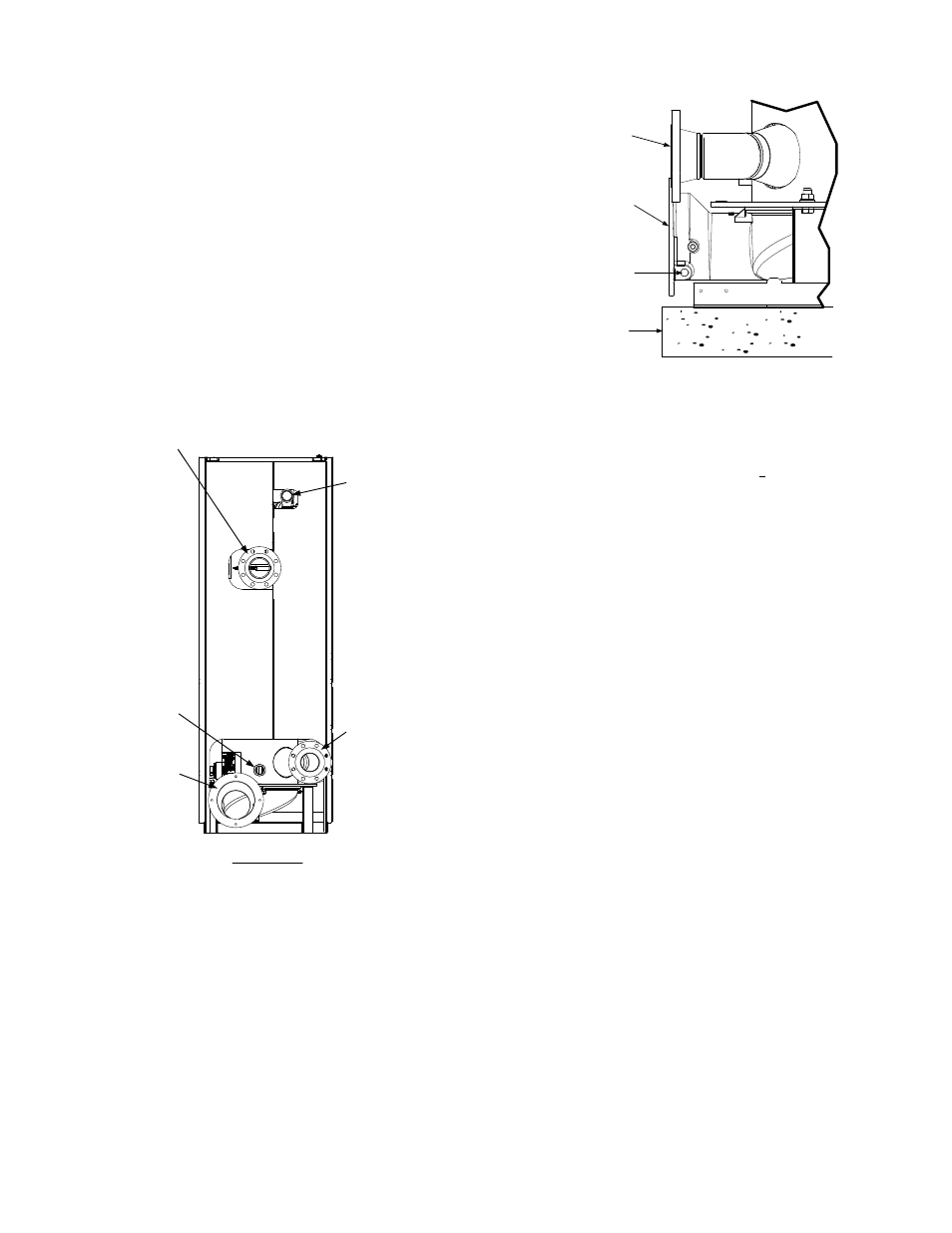
rear of the unit as shown in Figure 2-3. Refer to
Appendix F, Drawing AP-A-798 for additional
dimensional data.
2" GAS INLET
CONNECTION
BOILER RETURN
4" – 150# FLANGE
CONNECTION
BOILER SUPPLY
4" – 150# FLANGE
CONNECTION
EXHAUST
MANIFOLD
SHELL
DRAIN
VALVE
REAR VIEW
Figure 2-3
Supply and Return Locations
2.6 CONDENSATE DRAIN AND PIPING
The Boiler is designed to condense water vapor
from the flue products. Therefore, the installation
must have provisions for suitable drainage or
collection. A 1/2” NPT drain connection is
provided on the exhaust manifold as shown in
Figure 2-4.
EXHAUST
MANIFOLD
1/2” NPT
CONDENSATE
DRAIN
CONNECTION
HOUSE-
KEEPING
PAD
BOILER
RETURN
Figure 2-4
Condensate Drain Connection Location
A condensate drain trap (part no. 24060) is
shipped loose and must be installed at the rear
of the unit. The trap inlet and outlet contain
tapped 3/4” NPT ports. The actual installation
details for the condensate trap will depend on
the available clearances, housekeeping pad
height/dimensions and other prevailing condi-
tions at the site. However, the following
guidelines must be observed to ensure proper
condensate trap operation:
• The condensate trap inlet (Figure 2-5) must
be level with, or lower than the exhaust
manifold drain port.
• The condensate trap must be supported to
ensure that its base is level (horizontal).
• The trap must be removable for routine
maintenance. AERCO recommends that a
union be utilized between the exhaust
manifold condensate drain port and the trap
inlet port.
1. While observing the above guidelines,
connect the condensate trap inlet to the
exhaust manifold drain connection using the
appropriate piping components (nipples,
reducers, elbows, etc.) for the boiler
installation site.
2. At the condensate trap outlet, install a 3/4”
NPT nipple.
3. Connect a length of 1” I.D polypropylene
hose to the trap outlet and secure with a
hose clamp.
4. Route the hose on the trap outlet to a
nearby floor drain.