3 flame detector, 4 combustion calibration, 5 safety device testing – AERCO BMK 2.0 LN Nat. Gas June 2010 User Manual
Page 59: 6 burner assembly inspection, Maintenance
MAINTENANCE
NOTE
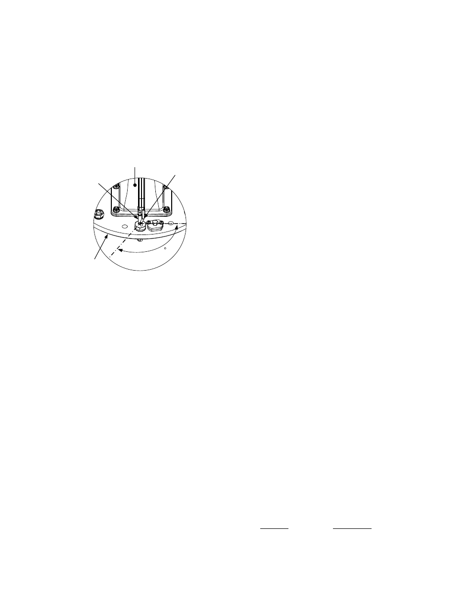
If a replacement ignitor-injector (part no.
58023) is being installed, a compression
nut containing a built-in ferrule will be
included with the replacement part. If
needed, 3 indexing washers are also
included These washers may be needed
to properly position the gas injector tube
of the ignitor-injector within the 120° angle
shown in Figure 7-3.
12
0
IGNITOR-
INJECTOR
GAS
INJECTOR
TUBE
BLOWER
BURNER
PLATE
Figure 7-3
Ignitor-Injector Orientation
8. Reinstall the ignitor-injector in the burner
plate. Torque to 15 ft-lbs. Do not over
tighten.
9. Connect the staged ignition assembly to the
gas injector tube of the ignitor-injector by
securing the compression nut to the elbow
of the staged ignition assembly.
10. Reconnect the ignitor-injector cable.
11. Reinstall the side and top panels on the unit.
7.3 FLAME DETECTOR
The flame detector (part no. 66006) is located
on the burner plate at the top of the unit (see
Figures 7-1 and 7-2). The flame detector may be
hot. Allow the unit to cool sufficiently before
removing the flame detector.
To inspect or replace the flame detector:
1. Set
the
ON/OFF switch on the control panel,
to the OFF position. Disconnect AC power
from the unit.
2. Remove the side and top panels from the
unit.
3. Disconnect the lead wire from the flame
detector.
4. Remove the two (2) screws securing the
flame detector to the plate (Figure 7-2). The
flame detector is secured to the burner plate
with one (1) #10-32 screw and one (1) #8-32
screw.
5. Remove the flame detector and gasket from
the burner plate.
6. Thoroughly inspect the detector. If eroded,
the detector should be replaced. Otherwise
clean the detector with a fine emery cloth.
7. Reinstall the flame detector and flame
detector gasket.
8. Reconnect the flame detector lead wire.
9. Reinstall the side and top panels on the unit.
7.4 COMBUSTION CALIBRATION
Combustion settings must be checked at the
intervals shown in Table 7-1 as part of the
maintenance requirements. Refer to Chapter 4
for combustion calibration instructions.
7.5 SAFETY DEVICE TESTING
Systematic and thorough tests of the operating
and safety devices should be performed to
ensure that they are operating as designed.
Certain code requirements, such as ASME
CSD-1, require that these tests be performed on
a scheduled basis. Test schedules must
conform to local jurisdictions. The results of the
tests should be recorded in a log book. See
Chapter 6-Safety Device Testing Procedures.
7.6 BURNER ASSEMBLY INSPECTION
The burner assembly (part no. 24176) is located
at the top of the unit's heat exchanger. The
burner assembly may be hot. Therefore, allow
the unit to cool sufficiently before removing the
burner assembly. It should be noted that the
complete burner assembly also includes the
blower and air/fuel valve in addition to the
Benchmark 2.0 Low NOx burner.
The following parts will be necessary for
reassembly after inspection:
Part No.
Description
81101
Burner Gaskets (2)
81048
Flame Detector Gasket
81068
Blower Gasket
7-3