10 start/stop levels, Control panel operating procedures – AERCO BMK 2.0 LN Nat. Gas June 2010 User Manual
Page 34
CONTROL PANEL OPERATING PROCEDURES
3-10
8. With the unit firing properly, it will be
controlled by the temperature controller
circuitry. The boiler’s VALVE POSITION will
be continuously displayed on the front panel
bargraph.
Once the demand for heat has been satisfied,
the Control Box will turn off the dual SSOV gas
valves. The blower relay will be deactivated and
the Air/Fuel Valve will be closed. Standby will
be displayed.
3.10 START/STOP LEVELS
The start and stop levels are the Air/Fuel Valve
positions (% open) that start and stop the unit,
based on load. These levels are Factory preset
as follows:
Start Level: 22%
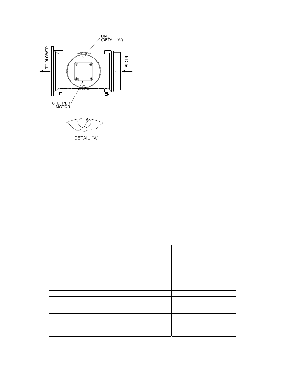
Figure 3-6.
Air/Fuel Valve In Ignition Position
Stop Level: 18%
Normally, these settings should not require
adjustment.
6. Up to 7 seconds will be allowed for ignition
to be detected. The igniter relay will be
turned off one second after flame is
detected.
Note that the energy input of the boiler is not
linearly related to the Air/Fuel Valve position.
Refer to Table 3-7 on the following page for the
relationship between the energy input and valve
open position (%) for a unit running on natural
gas.
7. After 2 seconds of continuous flame, Flame
Proven
will be displayed and the flame
strength will be indicated. After 5 seconds,
the current date and time will be displayed in
place of the flame strength.
Table 3-7.
Relationship Between Air/Fuel Valve Position and Energy Input For Unit Running On Natural Gas
Air/Fuel Valve Position
(% Open)
Energy Input
(BTU/Hr)
Boiler Energy Input
(% of Full Capacity)
0 0 0
10% 0 0
18%
(Stop Level)
100,000
5.0%
20% 202,000 10%
30% 428,000 21%
40% 705,000 35%
50% 956,000 48%
60% 1,390,000 70%
70% 1,770,000 89%
80% 1,890,000 95%
90% 1,960,000 98%
100% 2,000,000 100%