7 flame fault tests, 8 air flow fault tests, Safety device testing – AERCO BMK 2.0 LN Nat. Gas June 2010 User Manual
Page 54
SAFETY DEVICE TESTING
6. Press
the
CLEAR
button to reset the fault
7. The unit should start.
6.7 FLAME FAULT TESTS
Flame faults can occur during ignition or while
the unit is already running. To simulate each of
these fault conditions, proceed as follows:
1. Set
the
ON/OFF
switch to the OFF position.
2. Place the unit in the Manual Mode and set
the valve position between 25% and 30%.
3. Close the manual gas shutoff valve located
between the Safety Shut-Off Valve (SSOV)
and the Air/Fuel Valve (see Figure 6-3).
4. Set
the
ON/OFF
switch to the ON position to
start the unit.
5. The unit should shut down after reaching the
Ignition cycle and display FLAME LOSS
DURING IGN.
6. Open the valve previously closed in step 3
and press the CLEAR button.
7. Restart the unit and allow it to prove flame.
8. Once flame is proven, close the manual gas
valve located between the SSOV (Figure 6-
3) and the Air/Fuel Valve.
9. The unit should shut down and execute an
IGNITION RETRY
cycle by performing the
following steps:
(a) The unit will execute a shutdown purge
cycle for a period of 15 seconds and
display WAIT FAULT PURGE.
(b) The unit will execute a 30 second re-
ignition delay and display WAIT RETRY
PAUSE.
(c) The unit will then execute a standard
ignition sequence and display WAIT
IGNITION RETRY
.
10. Since the manual gas shutoff valve is still
closed, the unit will shut down and display
FLAME LOSS DURING IGNITION
following
the IGNITION RETRY cycle.
11. Open the valve previously closed in step 8.
12. Press the CLEAR button. The unit should
restart and fire.
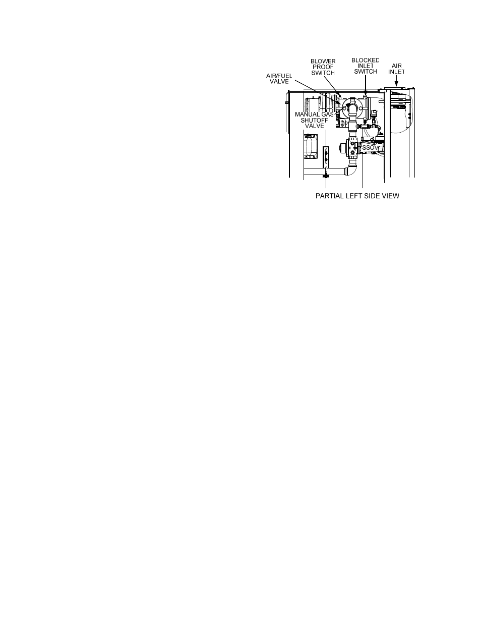
Figure 6-3
Manual Gas Shut-Off Valve Location
6.8 AIR FLOW FAULT TESTS
These tests check the operation of the Blower
Proof Switch and Blocked Inlet Switch shown in
Figure 6-3.
1. Disable the blower output drive voltage as
follows:
(a) Press the MENU key until CONFIGUR-
ATION MENU
is displayed.
(b) Press
the
▲ arrow key until the ANA-
LOG OUTPUT
function is displayed,
then press the CHANGE key.
(c) Press
the
▼ arrow key until OFF is
displayed, then press the ENTER key.
2. Start the unit in the Manual Mode at a valve
position between 25% and 30%.
3. The unit should shut down and execute an
IGNITION RETRY
cycle by performing the
following steps:
(a) The unit will execute a 30 second re-
ignition delay and display WAIT RETRY
PAUSE.
(b) The unit will then execute a standard
ignition sequence and display WAIT
IGNITION RETRY
.
4. The unit should perform two IGNITION
RETRY
cycles and then shut down on the
third successive ignition attempt. The unit
will display AIRFLOW FAULT DURING
PURGE.
6-4