Initial start-up – AERCO BMK 2.0 LN Nat. Gas June 2010 User Manual
Page 37
INITIAL START-UP
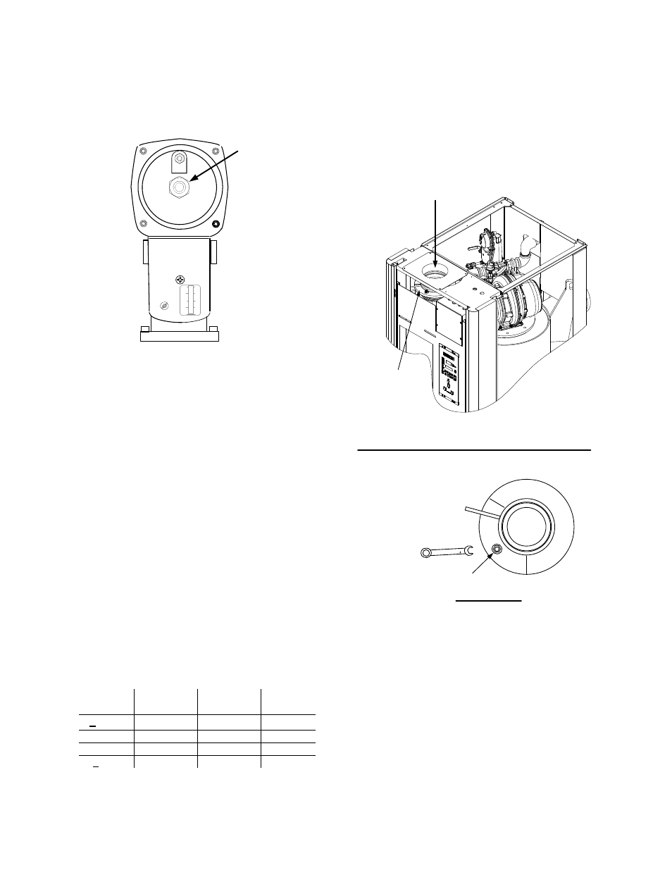
gas pressure adjustment screw (Figure 4-3).
Make gas regulator adjustments using a flat-
tip screwdriver to obtain 2.8” W.C.
BRASS HEX
HEAD CAP
(REMOVE TO
ACCESS GAS
PRESSURE
ADJUSTMENT
SCREW)
SSOV ACTUATOR
Figure 4-3
Gas Pressure Adjustment Screw
Location
11. Increase the valve position to 100% and
verify that the gas pressure downstream of
the SSOV remains at 2.8” W.C. Readjust
pressure if necessary.
12. With the valve position at 100%, insert the
combustion analyzer probe into the flue
probe opening and allow enough time for the
combustion analyzer to settle.
13. Compare the measured oxygen level to the
oxygen range for the inlet air temperature
shown in Table 4-1. Also, ensure that the
carbon monoxide (CO) and nitrogen oxide
(NOx) readings do not exceed the values
shown.
Table 4-1
Combustion Oxygen Levels for a 100%
Valve Position
Inlet Air
Temp
Oxygen %
± 0.2
Carbon
Monoxide
NOx
>100°F
4.8 %
<100 ppm
<30 ppm
90°F
5.0 %
<100 ppm
<30 ppm
80°F
5.2 %
<100 ppm
<30 ppm
<70°F
5.3 %
<100 ppm
<30 ppm
14. If necessary, adjust the iris air damper
shown in Figure 4-4 until the oxygen level is
within the range specified in Table 4-1.
15. Once the oxygen level is within the specified
range at 100%, lower the valve position to
80%.
AIR
INLET
IRIS AIR
DAMPER
(SEE VIEW “A”)
USE 1/2"
WRENCH TO
INCREASE (CW)
OR DECREASE
(CCW) INLET AIR
IRIS ADJUSTMENT
VIEW A - A
Figure 4-4
Iris Air Damper Location/Adjustment
NOTE
The remaining combustion calibration
steps are performed using the
Combustion Cal Menu
included in the C-
More Control System. The combustion
calibration control functions will be used
to adjust the oxygen level (%) at valve
positions of 80%, 60%, 45%, 30% and
18% as described in the following steps.
These steps assume that the inlet air
temperature is within the range of 50°F to
100°F.
4-3