9 ssov proof of closure switch, 10 purge switch open during purge, Safety device testing – AERCO BMK 2.0 LN Nat. Gas June 2010 User Manual
Page 55
SAFETY DEVICE TESTING
5. Re-enable the blower output drive voltage
by performing the following steps:
(a) Press the MENU key until CONFIGUR-
ATION MENU
is displayed.
(b) Press
the
▲ arrow key until the ANA-
LOG OUTPUT
function is displayed,
then press the CHANGE key.
(c) Press
the
▲ arrow key until VALVE
POSITION 0-10V
is displayed, then
press the ENTER key.
6. Once the unit has proved flame, turn off the
blower by going to the Configuration Menu,
Analog Output
menu item and select OFF.
7. The Blower Proof Switch will open and the
blower should stop. The unit should shut
down and display AIRFLOW FAULT
DURING RUN
.
8. Go to the Configuration Menu, Analog
Output
item and select VALVE POSITION 0-
10v
.
9.
Press the CLEAR button. The unit should
restart.
10. Next, check the Blocked Inlet Switch by first
noting the current position of the Iris Air
Damper and then closing the Damper to
position 8.
11. .The unit should shut down and again
display AIRFLOW FAULT DURING RUN.
12. Return the Iris Air Damper to its previous
setting.
13. Press the CLEAR button. The unit should
restart.
6.9 SSOV PROOF OF CLOSURE SWITCH
The SSOV shown in Figure 6-1 contains the
proof of closure switch. The proof of closure
switch circuit is checked as follows:
1. Set the unit’s ON/OFF switch to the OFF
position.
2. Place the unit in Manual Mode and set the
valve position between 25% and 30%
3. Refer to Figure 6-1 and locate the SSOV.
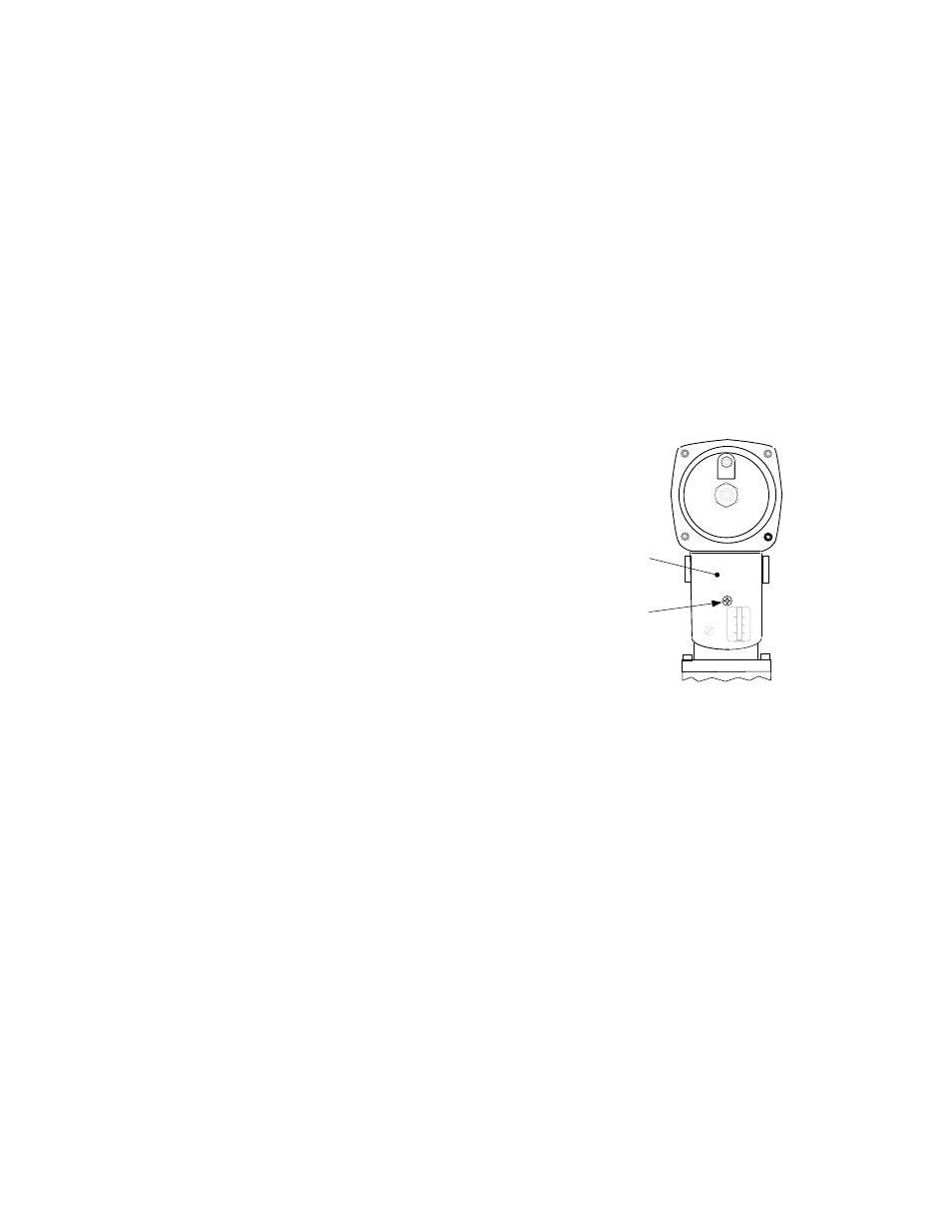
4. Remove the cover from the SSOV by
loosening the screw shown in Figure 6-4. Lift
off the cover to access the terminal wiring
connections.
5. Disconnect wire #148 from the SSOV to
“open” the proof of closure switch circuit.
6. The unit should fault and display SSOV
SWITCH OPEN.
7. Replace wire #148 and press the CLEAR
button.
8. Set the ON/OFF switch to ON to start the
unit.
9. Remove the wire again when the unit
reaches the purge cycle and PURGING is
displayed.
10. The unit should shut down and display
SSOV FAULT DURING PURGE.
11. Replace the wire on the SSOV and press
the CLEAR button. The unit should restart.
ACTUATOR
COVER
SCREW
SSOV
ACTUATOR
COVER
Figure 6-4
SSOV Actuator Cover Location
6.10 PURGE SWITCH OPEN DURING
PURGE
The Purge Switch (and Ignition Switch) is
located on the Air/Fuel Valve. To check the
switch, proceed as follows:
1. Set the unit’s ON/OFF switch to the OFF
position. Place the unit in manual mode and
set the valve position between 25% and
30%.
2. Remove the Air/Fuel Valve cover by rotating
the cover counterclockwise to unlock it and
then lift up (see Figure 6-5).
3. Remove one of the two wires (#171 or #172)
from the Purge Switch (Figure 6-6).
4. Initiate a unit start sequence.
6-5