Safety device testing – AERCO BMK 1.5 LN Dual Fuel Jan 2009 User Manual
Page 49
SAFETY DEVICE TESTING
6. Open the valve previously closed in step 3
and press the CLEAR button.
7. Restart the unit and allow it to prove flame.
8. Once flame is proven, close the manual gas
valve located between the SSOV and the
Air/Fuel Valve.
9. The unit should shut down and display
FLAME LOSS DURING RUN.
10. Open the valve previously closed in step 8.
11. Press the CLEAR button. The unit should
restart and fire.
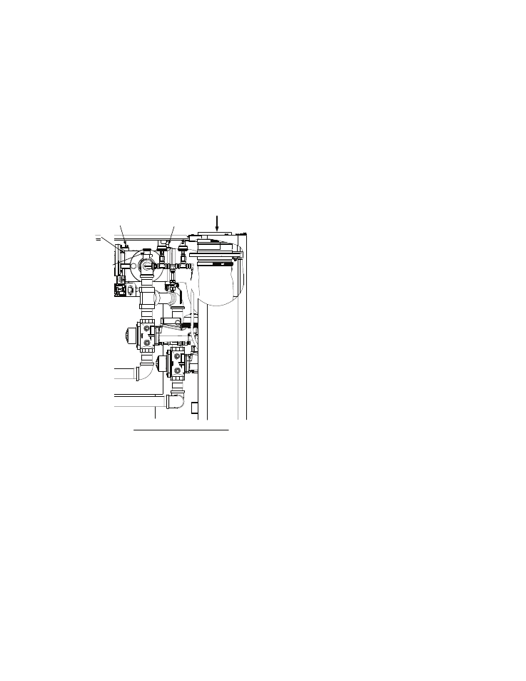
AIR INLET
AIR/FUEL
VALVE
BLOCKED
INLET
SWITCH
MANUAL GAS
SHUTOFF
VALVE
BLOWER
PROOF
SWITCH
PARTIAL LEFT SIDE VIEW
Figure 6-3
Manual Gas
ve Location
6.10 AIR FLOW FAULT TESTS
lower
1. Start the unit in the Manual Mode at a firing
e, remove the
Shut-Off Val
These tests check the operation of the B
Proof Switch and Blocked Inlet Switch shown in
Figure 6-3.
8.
rate between 25% and 30%.
2. Once the unit has proved flam
memory stick from the Variable Frequency
Drive (VFD).
3. The Blower Proof Switch will open and the
blower should stop. The unit should shut
down and display AIRFLOW FAULT
DURING RUN.
4. Replace the memory stick in the VFD.
5.
Press the CLEAR button. The unit should
restart.
6. Next, check the Blocked Inlet Switch by
closing the Iris Air Damper to position 8.
7. .The unit should shut down and again
display AIRFLOW FAULT DURING RUN.
8. Return the Iris Air Damper to its previous
setting.
9. Press the CLEAR button. The unit should
restart.
6.11 SSOV PROOF OF CLOSURE
SWITCH
This test can be performed when the unit is set
up to run on either natural gas or propane fuel.
Both the Natural Gas and Propane SSOVs
contain proof of closure switches which are
wired in series.
1. Set the unit’s ON/OFF switch to the OFF
position.
2. Place the unit in Manual Mode and set the
firing rate between 25% and 30%
3. Refer to Figure 6-1 and locate the Natural
Gas SSOV.
4. Remove the cover from the SSOV by
loosening the screw shown in Figure 6-4. Lift
off the cover to access the terminal wiring
connections.
5. Disconnect wire #148 from the SSOV to
“open” the proof of closure switch circuit.
6. The unit should fault and display SSOV
SWITCH OPEN.
7. Replace wire #148 and press the CLEAR
button.
Set
the
ON/OFF switch to ON to restart the
unit.
9. Remove the wire again when the unit
reaches the purge cycle and PURGING is
displayed.
10. The unit should shut down and display
SSOV FAULT DURING PURGE.
6-5