Installation – AERCO BMK 1.5 LN Dual Fuel Jan 2009 User Manual
Page 13
INSTALLATION
2-3
If installing a Combination Control Panel (CCP)
system, it is important to identify the
Combination Mode Boilers in advance and place
them in the proper physical location. Refer to
Chapter 5 for information on Combination Mode
Boilers.
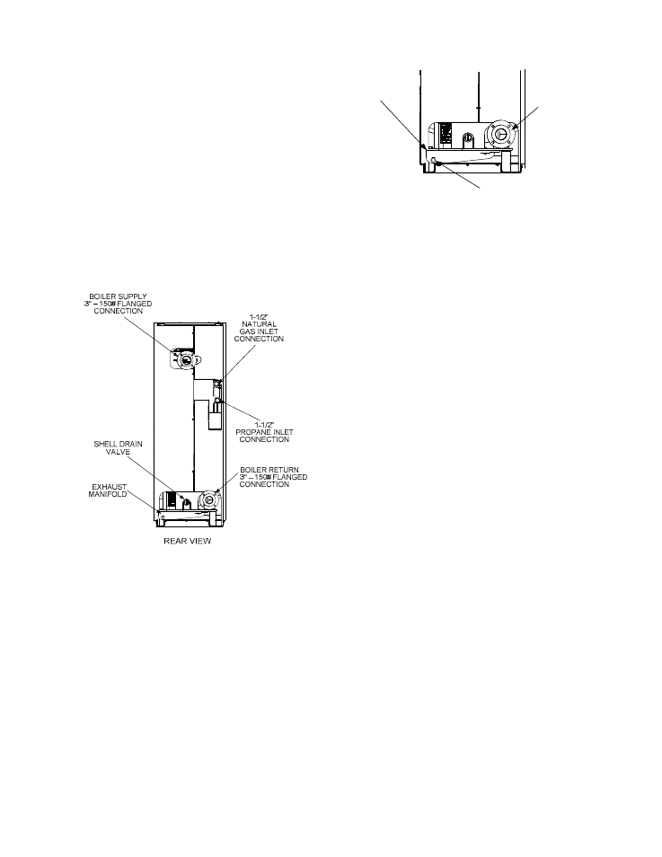
2.5 SUPPLY AND RETURN PIPING
The Benchmark 1.5 Boiler utilizes 3” 150#
flanges for the water system supply and return
piping connections. The physical location of the
supply and return piping connections are on the
rear of the unit as shown in Figure 2-3. Refer to
Appendix F, Drawing AP-A-832 for additional
dimensional data.
Figure 2-3
Supply and Return Locations
2.6 CONDENSATE DRAIN
The Benchmark 1.5 Boiler is designed to
condense water vapor from the flue products.
Therefore, the installation must have provisions
for suitable condensate drainage or collection.
The drain pipe located on the exhaust manifold
must be connected to a condensate trap which
is packed separately within the unit’s shipping
container.
The procedure to install and connect the
condensate drain is provided in paragraph 2.6.1.
EXHAUST
MANIFOLD
PARTIAL REAR VIEW
CONDENSATE DRAIN
CONNECTION
BOILER
RETURN
Figure 2-4
Condensate Drain Connection Location
2.6.1 Exhaust Manifold Condensate
Drain
The exhaust manifold drain pipe connection
shown in Figure 2-4, must be connected to a
condensate drain trap external to the unit. Refer
to Figure 2-5 and install the trap as follows:
1. Position the supplied condensate trap (part
no. 24060) on the floor at the rear of the
unit.
2. Install 3/4” NPT nipples in the tapped inlet
and outlet of the condensate trap.
3. Attach a length of 1” I.D. hose between the
exhaust manifold drain pipe and the inlet
side of the condensate trap (Figure 2-5).
Secure both ends of the hose with clamps.
4. Connect a second length of 1” I.D.
polypropylene hose to the outlet side of the
condensate trap and route it to a nearby
floor drain.
If a floor drain is not available, a condensate
pump can be used to remove the condensate to
drain. The maximum condensate flow rate is 20
GPH. The condensate drain trap, associated
fittings and drain lines must be removable for
routine maintenance. Therefore, DO NOT hard
pipe.