Control panel operating procedures – AERCO BMK 1.5 LN Dual Fuel Jan 2009 User Manual
Page 28
CONTROL PANEL OPERATING PROCEDURES
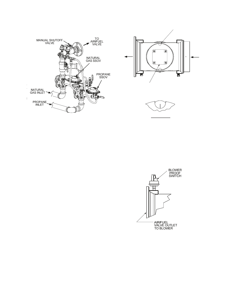
Figure 3-3.
SSOV Locations
3. With all required safety device switches
closed, a purge cycle will be initiated and the
following events will occur:
(a) The Blower relay energizes and turns
on blower.
(b) The Air/Fuel Valve rotates to the full-
open purge position and closes purge
position switch. The dial on the Air/Fuel
Valve (Figure 3-4) will read 100 to
indicate that it is full-open (100%).
(c) The FIRE RATE bargraph will show
100%.
(d) The VFD applies voltage to the blower
which then starts to rotate.
4. Next, the blower proof switch on the Air/Fuel
Valve (Figure 3-5) closes. The display will
show Purging and indicate the elapsed time
of the purge cycle in seconds. The normal
(default) time for the purge cycle is 7
seconds.
100
DETAIL “A”
T
O
B
L
OWE
R
AI
R I
N
DIAL
(DETAIL “A”)
STEPPER
MOTOR
Figure 3-4.
Air/Fuel Valve In Purge Position
5. Next, the blower proof switch on the Air/Fuel
Valve (Figure 3-5) closes. The display will
show Purging and indicate the elapsed time
of the purge cycle in seconds. The normal
(default) time for the purge cycle is 7
seconds.
Figure 3-5.
Blower Proof Switch
3-8