Initial start-up, Propane natural gas of f – AERCO BMK 1.5 LN Dual Fuel Jan 2009 User Manual
Page 33
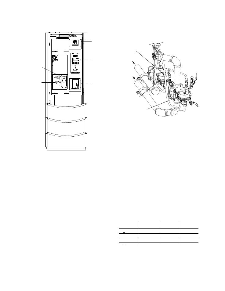
INITIAL START-UP
PROPANE
NATURAL
GAS
OF F
POWER
BOX
CONTROL
PANEL
I/O BOX
FUEL
SELECTOR
SWITCH
VFD
Figure 4-3
Front View With Door Removed
11. Locate the Variable Frequency Drive (VFD)
on the front of the unit behind the panel door
(Figure 4-3). Insert the “LogicStick” with the
“NATURAL GAS” label in the slot on the
front of the VFD.
12. Set the ON/OFF switch to the ON position.
13. Access the control panel Configuration
Menu and ensure that the Max Fire Rate is
set to 100%. (Refer to Chapter 3, para. 3.3
for instructions on changing menu options).
14. Change the fire rate to 29% using the ▲
arrow key. The unit should begin its start
sequence and fire.
15.
Next, verify that the gas pressure
downstream of the Natural Gas SSOV is 3”
W.C. for both FM and IRI gas trains. If gas
pressure adjustment is required, refer to
Figure 4-4 and remove the brass hex nut on
the SSOV actuator containing the gas
pressure regulator. (For IRI gas trains, the
regulator is on the downstream SSOV).
Make gas regulator adjustments using a flat-
tip screwdriver to obtain 3” W.C.
NATURAL
GAS INLET
PROPANE
INLET
PROPANE
SSOV WITH
REGULATOR
NATURAL GAS
SSOV WITH
REGULATOR
BRASS HEX HEAD CAP
(REMOVE TO ADJUST
NATURAL GAS
REGULATOR)
Figure 4-4
Regulator Adjustment Screw Location
16. Raise the firing rate to 100% and verify that
the gas pressure downstream of the SSOV
remains at 3” W.C. Readjust pressure if
necessary.
17. With the firing rate at 100%, insert the
combustion analyzer probe into the vent
probe port opening and allow enough time
for the combustion analyzer to settle.
18. Compare the measured oxygen level to the
oxygen range for the inlet air temperature
shown in Table 4-1. Also, ensure that the
carbon monoxide (CO) and nitrogen oxide
(NOx) readings do not exceed the values
shown.
Table 4-1
Combustion Oxygen Levels for a 100%
Firing Rate
Inlet Air
Temp
Oxygen %
± 0.2
Carbon
Monoxide
NOx
>100°F
4.8 %
<100 ppm
<30 ppm
90°F
5.0 %
<100 ppm
<30 ppm
80°F
5.2 %
<100 ppm
<30 ppm
<70°F
5.3 %
<100 ppm
<30 ppm
19. If necessary, adjust the iris air damper
shown in Figure 4-5 until the oxygen level is
within the range specified in Table 4-1.
4-3