Benchmark 1.5ln low nox boiler, Gf-120 – AERCO BMK 1.5 LN October 2012 User Manual
Page 86
CHAPTER 7
MAINTENANCE
Page 86 of 166 AERCO International Inc. • 100 Oritani Dr. • Blauvelt, NY 10913 • Ph: 800-526-0288 PR1:10/18/12
Benchmark 1.5LN Low NOx Boiler
Installation, Operation and Maintenance Manual
GF-120
OMM-0041 0E
Set the ON/OFF switch on the control panel, to the OFF position. Disconnect AC power
1.
from the unit and turn off the gas supply.
Remove the side and top panels from the unit.
2.
Disconnect the lead wire from the flame detector installed on the burner plate. See
3.
Figure 7-4.
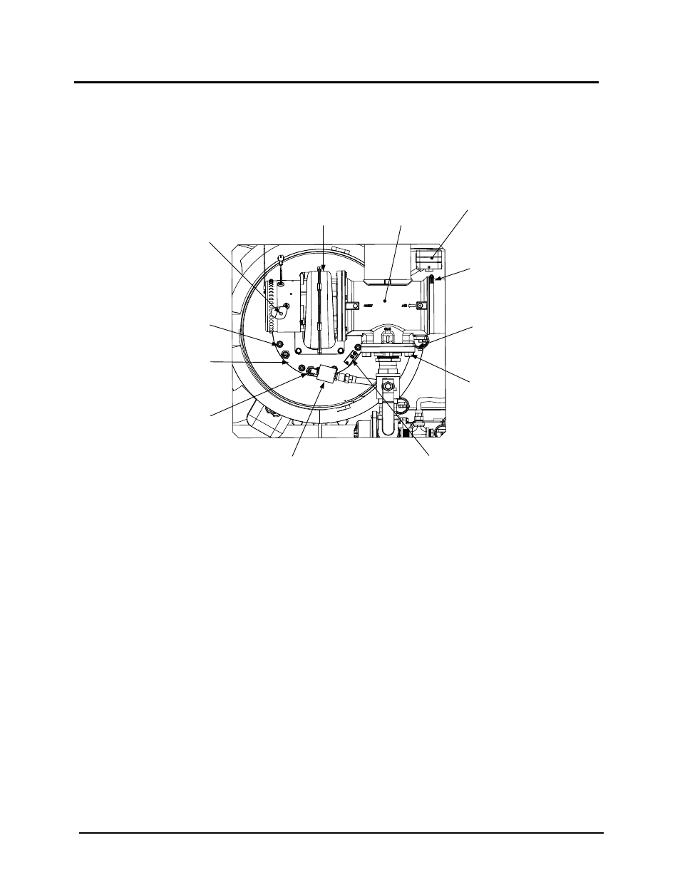
BLOWER
PROOF
SWITCH
BURNER
PLATE
BLOWER
IGNITER-
INJECTOR
HOSE
CLAMP
FLAME
DETECTOR
STAGED
IGNITION
ASSEMBLY
3/8-16
HEX NUTS
(8)
1/2" BOLTS
& NUTS (4)
AIR/FUEL
VALVE
BLOCKED
INLET
SWITCH
10-32 x 1 /2" LG
GROUNDING
SCREW
Figure 7-4: Burner Assembly Mounting Details
Remove the two (2) screws securing the flame detector to the plate. The flame detector
4.
is secured to the burner plate with one (1) #10-32 screw and one (1) #8-32 screw.
Remove the flame detector and gasket from the burner plate.
5.
Disconnect the cable from the igniter-injector.
6.
Using a 7/16” open-end wrench, disconnect the compression nut securing the gas
7.
injector tube of the igniter-injector to the elbow of the staged ignition assembly (see
Figure 7-2). Disconnect the staged ignition assembly from the igniter-injector.
Next, loosen and remove the igniter-injector from the burner plate using a 1" open-end
8.
wrench.
Disconnect the unit wiring harness connectors from the air/fuel valve and blower motor.
9.
Disconnect the wire leads connected to the blower proof switch and blocked inlet switch
10.
(Figures 7-4 & 7-5).
Remove the 10-32 x 1/2" long. grounding screw from the burner plate (Figures 7-4 and
11.
7-5).
Disconnect the gas train from the air/fuel valve by removing the four (4) 1/2” bolts and
12.
nuts (Figure 7-4).