Benchmark 1.5ln low nox boiler, Gf-120 – AERCO BMK 1.5 LN October 2012 User Manual
Page 52
CHAPTER 4
INITIAL START-UP
Page 52 of 166 AERCO International Inc. • 100 Oritani Dr. • Blauvelt, NY 10913 • Ph: 800-526-0288 PR1:10/18/12
Benchmark 1.5LN Low NOx Boiler
Installation, Operation and Maintenance Manual
GF-120
OMM-0041 0E
Increase the valve open position to 100% and verify that the gas pressure downstream
11.
of the SSOV remains at 3” W.C. Readjust pressure if necessary.
With the valve position at 100%, insert the combustion analyzer probe into the flue probe
12.
opening and allow enough time for the combustion analyzer to settle.
Compare the measured oxygen level to the oxygen range for the inlet air temperature
13.
shown in Table 4-1. Also, ensure that the carbon monoxide (CO) and nitrogen oxide
(NOx) readings do not exceed the values shown.
Table 4-1: Combustion Oxygen Levels for a
100% Air/Fuel Valve Position
Inlet Air
Temp
Oxygen
%
± 0.2
Carbon
Monoxid
e
NOx
>100°F
4.8 %
<100 ppm
<30 ppm
90°F
5.0 %
<100 ppm
<30 ppm
80°F
5.2 %
<100 ppm
<30 ppm
<70°F
5.3 %
<100 ppm
<30 ppm
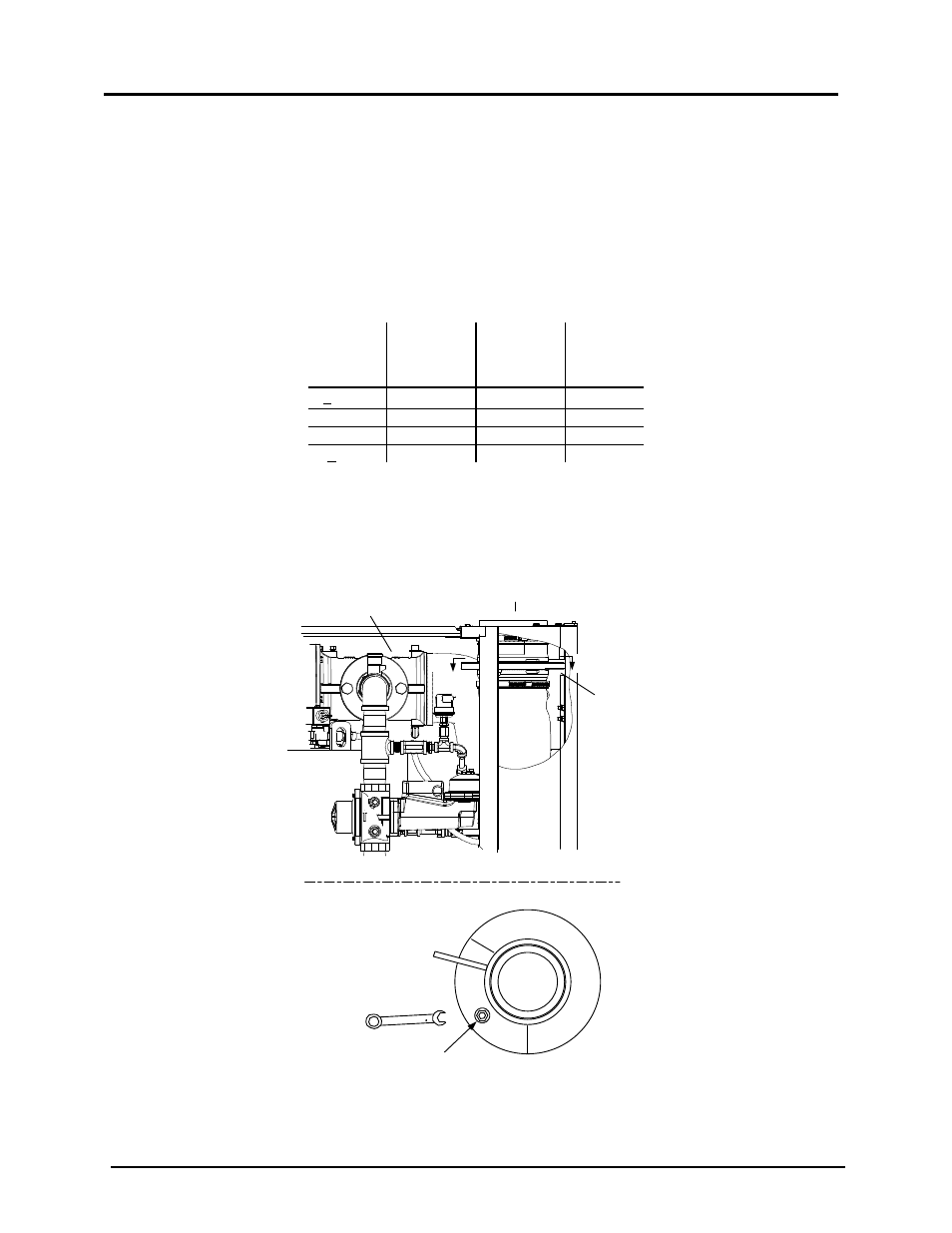
If necessary, adjust the iris air damper shown in Figure 4-5 until the oxygen level is
14.
within the range specified in Table 4-1.
Once the oxygen level is within the specified range at 100%, lower the valve position to
15.
80%.
USE 1/2"
WRENCH TO
INCREASE (CW)
OR DECREASE
(CCW) INLET AIR
IRIS
ADJUSTMENT
VIEW A - A
AIR INLET
IRIS AIR
DAMPER
FRONT
A
A
AIR/FUEL
VALVE
Figure 4-5: Iris Air Damper Location/Adjustment