1 electrical power requirements, Gf-120, Benchmark 1.5ln low nox boiler – AERCO BMK 1.5 LN October 2012 User Manual
Page 21
CHAPTER 2
INSTALLATION
PR1: 10/18//12 AERCO International Inc. • 100 Oritani Dr. • Blauvelt, NY 10913 • Ph: 800-526-0288 Page 21 of 166
GF-120
OMM-0041 0E
Benchmark 1.5LN Low NOx Boiler
Installation, Operation and Maintenance Manual
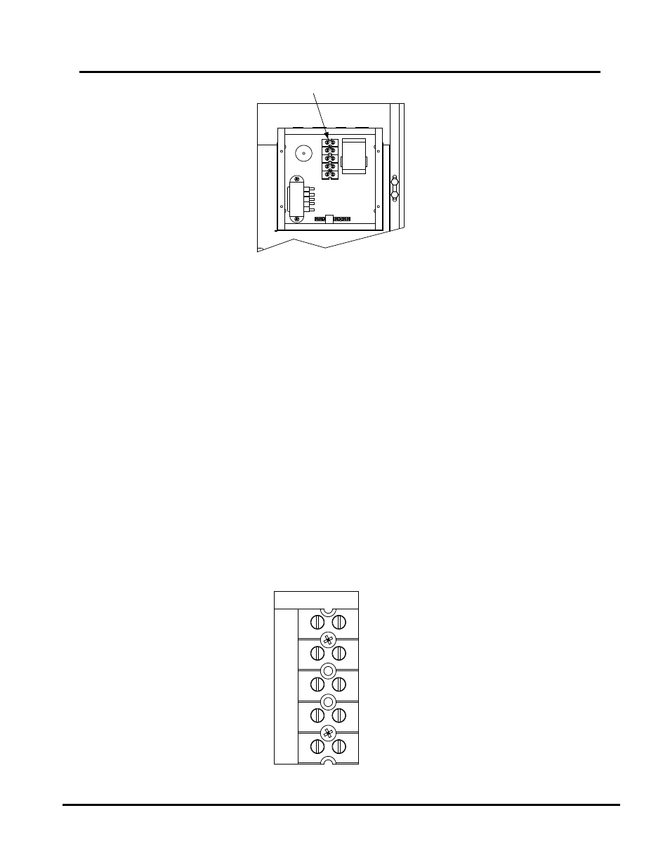
UPPER RIGHT CORNER OF FRONT PANEL
TERMINAL BLOCK
Figure 2-7: AC Input Terminal Block Location
2.8.1
Electrical Power Requirements
The AERCO Benchmark 1.5 Boiler accepts 120 VAC, single-phase, 60 Hz @ 20 A. The Power
Box contains a terminal block as shown in Figure 2-8. In addition, a wiring diagram showing the
required AC power connections is provided on the front cover of the Power Box.
Each Benchmark 1.5 Boiler must be connected to a dedicated electrical circuit. NO OTHER
DEVICES SHOULD BE ON THE SAME ELECTRICAL CIRCUIT AS THE BENCHMARK
BOILER.
A double-pole switch must be installed on the electrical supply line in an easily accessible
location to quickly and safely disconnect electrical service. DO NOT attach the switch to sheet
metal enclosures of the unit.
After placing the boiler in service, the ignition safety shutoff device must be tested. If an external
electrical power source is used, the installed boiler must be electrically bonded to ground in
accordance with the requirements of the authority having jurisdiction. In the absence of such
requirements, the installation shall conform to National Electrical Code (NEC), ANSI/NFPA 70
and/or the Canadian Electrical Code (CEC) Part I, CSA C22.1 Electrical Code.
For electrical power wiring diagrams, see the AERCO Benchmark 1.5 Electrical Power Wiring
Guide, (GF-4060).
GND
NEU
L1
120 VAC, 1 PHASE
Figure 2-8: AC Terminal Block Configurations