1 exhaust manifold condensate drain, Gf-120, Benchmark 1.5ln low nox boiler – AERCO BMK 1.5 LN October 2012 User Manual
Page 17
CHAPTER 2
INSTALLATION
PR1: 10/18//12 AERCO International Inc. • 100 Oritani Dr. • Blauvelt, NY 10913 • Ph: 800-526-0288 Page 17 of 166
GF-120
OMM-0041 0E
Benchmark 1.5LN Low NOx Boiler
Installation, Operation and Maintenance Manual
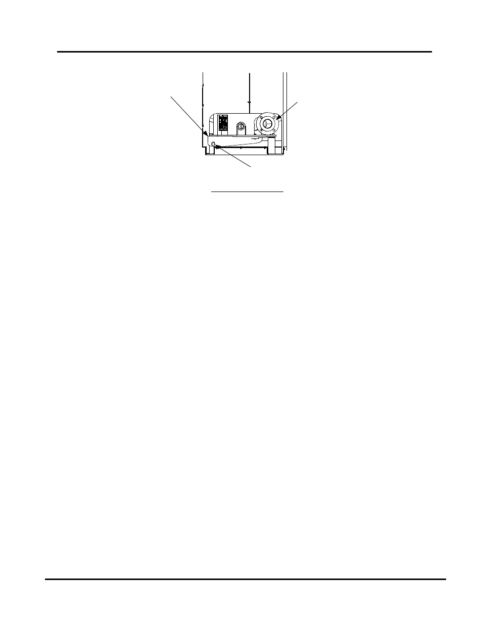
EXHAUST
MANIFOLD
PARTIAL REAR VIEW
CONDENSATE DRAIN
CONNECTION
BOILER
RETURN
Figure 2-4: Condensate Drain Connection Location
2.6.1
Exhaust Manifold Condensate Drain
The exhaust manifold drain pipe connection shown in Figure 2-4, must be connected to a
condensate drain trap external to the unit.
NOTE
There are two different types of condensate traps that may be used in; an
older style without built-in adapter, and a newer style with a built-in adapter
(see Figure 2-5). Installation is the same (1/4” threads are inside built-in
adapter on newer style).
Refer to Figure 2-5 and install the trap as follows:
Install 3/4” NPT nipples in the tapped inlet and outlet of the condensate trap (part no.
1.
24060).
Install a third 3/4” NPT nipple in the tapped condensate outlet of the exhaust manifold.
2.
Connect the exhaust manifold nipple to the condensate trap inlet using a female union.
3.
install a suitable support under the condensate trap and ensure that the trap is level.
4.
Connect a length of 1” I.D. polypropylene hose (part no. 91030) to the nipple on the
5.
outlet side of the condensate trap and secure it with a hose clamp.
Route the hose on the trap outlet to a nearby floor drain.
6.
If a floor drain is not available, a condensate pump can be used to remove the condensate to
drain. The maximum condensate flow rate is 20 GPH. The condensate drain trap, associated
fittings and drain lines must be removable for routine maintenance.