Foreign safety precautions, Checking the package contents, Part names and functions – KEYENCE SR-500 Series User Manual
Page 2: Connection and wiring method
2
E SR-500-IM
Precautions on UL certificate
The SR-500 Series complies with the following UL and CSA standards. The
equipment has received UL and C-UL certificate.
• Approved standard:
UL508 (Listed), UL60950-1 (R/C)
• UL File No:
E207185, E167973
• UL category:
NRAQ/NRAQ7, NWGQ2/NWGQ8
• SR-500 Series must use a Class 2 power source according to NEPA70
(NEC: National Electrical Code).
• Pollution degree: 2
• Overvoltage category: I
Precautions on CE marking
The SR-500 Series meets the requirements for the EMC Directive when used
with the following conditions and the CE marking is applied.
• Applicable standard (EMI):
EN55011, Class A
EN55022, Class B
• Applicable standard (EMS):
EN61000-6-2
EN61000-6-1
* Use communication cables and power cables no longer than 30m.
Precautions on FCC
The SR-500 Series complies with the following FCC regulation.
• FCC Part 15, SubPart B, Class A, Digital devices
Precautions on Canada IC (Industry Canada) regulations
The SR-500 Series complies with the following IC regulation.
• ICES-003, Class A, Digital devices
SR-500 Series connector pin position
* The shielded wire is directly connected to the common GND.
Foreign Safety Precautions
Checking the Package Contents
1
E SR-500-IM
2D Code Reader
SR-500 Series
Instruction Manual
General cautions
• Take substantial safety measures to avoid any damage in the unlikely event
of a problem occurring.
• Do not modify the SR-500 Series, or use it in any way other than described
in the specifications.
• When the SR-500 Series is used in combination with other devices, func-
tions and performance may be degr aded, depending on the operating
conditions and surrounding environment.
• Parts of this manual may not be used or duplicated without express per-
mission.
• The contents of his manual are subject to change without notice.
Important notes
When planning to use the SR-500 Series in situations or environments
described below, use it with ample margins in terms of ratings and functions,
and take appropriate failsafes and other safety measures.
• Usage in situations or environments other than those described in this
manual.
• Usage with nuclear power controls, railroad installations, aircraft installa-
tions, automotive equipment, combust ion equipment, medical equipment,
recreational equipment, or safety devices.
• Applications that are determined to have a large influence on life or prop-
erty, and additional safety measures are desired.
Safety precautions on laser product
The 2D Code Reader SR-500 Series uses a visible semiconductor laser as a
target pointer for adjusting the reading position.
This laser has a wavelength of 655nm and is classified as a Class 1 laser
under IEC standards (IEC60825-1: "Safety of Laser Products").
*
The laser classification for FDA(CDRH) is implemented based on IEC60825-1 in
accordance with the requirements of Laser Notice No.50.
Operating Precautions
Danger
Failure to follow instructions may lead to death or serious
injury.
Warning
Failure to follow instructions may lead to injury.
Caution
Failure to follow instructions may lead to product damage or
malfunctions.
Note
Provides additional information on proper operations that can
be easily mistaken.
Reference
Provides advanced and useful information for operation.
Safety Information for SR-500 Series
Caution
Use of controls or adjustments or performance of procedures
other than those specified herein may result in hazardous
radiation exposure.
Item
SR-500/510
Wavelength
655nm
Output
90μW
Pulse width
200μs
Laser Class
Class 1 Laser Product
(IEC60825-1, FDA(CDRH) Part1040.10*)
Warning
• Follow the instructions mentioned in this manual.
Otherwise, injury to the human body (eyes and skin) may
result.
Precautions on class 1 laser products
• Do not disassemble this product. Laser emission from
this product is not automatically stopped when it is
disassembled.
• Do not stare into the beam.
Caution
• Do not use a voltage other than 5VDC with the SR-500
Series. Doing so may lead to damage on the unit.
When using the dedicated communication units (NX-50
Series, N-R2/R4/UB/L1, or DV-90 Series), use a power
supply within the appropriate range for each unit.
• Be sure to turn the power off to devices attached to the
SR-500 Series when you plug or unplug the cables. Failure
to do so may cause damage to the SR-500 Series.
• Do not disassemble or modify the SR-500 Series. Doing so
may lead to damage on the unit.
• Keep the cables away from high-tension cables or power
sources. Otherwise, noise could cause malfunctions or
accidents.
• The SR-500 Series is a
precision instrument. Do
not apply shock to the
instrument or drop it. Be
especially careful when
transporting or installing the
unit.
• Do not hold the SR-500
Series by its cable. The
units may become
damaged if they strike
each other.
• Do not allow water, oil, dust, or other foreign substances to
stick to the scanner. This may cause read errors. Use a
soft, dry cloth to wipe any substances from the scanner.
(Do not use a cloth dipped in alcohol or other cleaning
substance.)
96M11012
Main unit
Instruction Manual
Mounting bracket ..... 1
Insulating spacer ......2
Washer .....................2
Installation
screw (M3) ................3
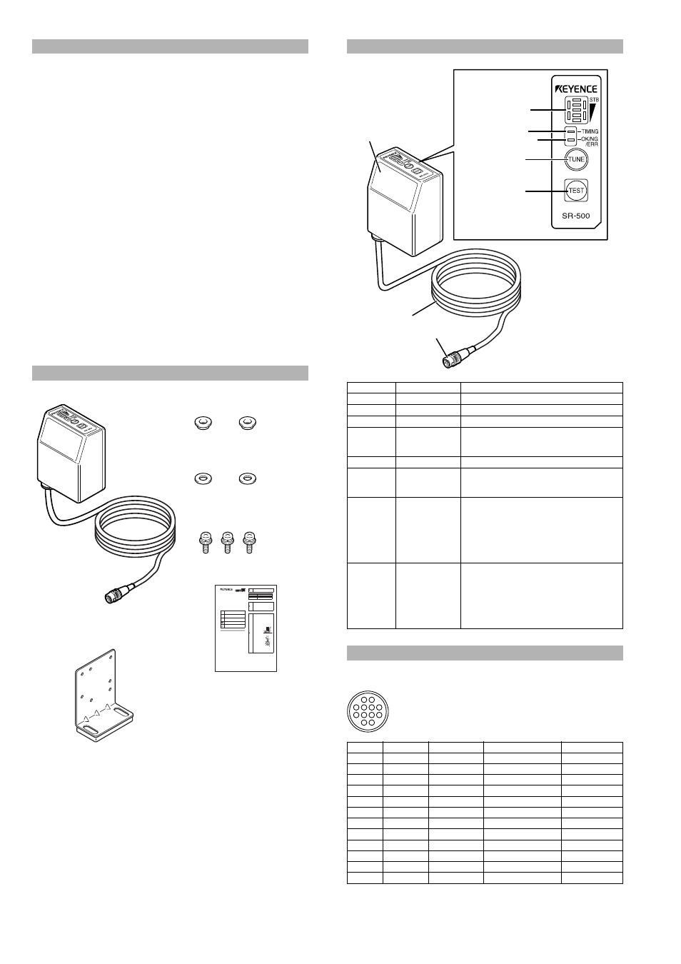
Part Names and Functions
Number
Name
Function
Window
Reads 2D codes and barcodes.
Cable
Cable is 1.8m long.
Connector
Connects to the communication unit.
Multiple LED
indicator
Displays the operation statuses, including the
parameter number during decoding, reading
stability, and operation mode.
Timing LED
Lights when the timing input is on.
OK/NG/ERR
LED
• Lights green when the output is OK.
• Lights orange when the output is NG.
• Lights red when the output is ERR.
TUNE switch
Use this switch to perform the following operations:
• Light read position adjustment laser pointer
• Display registered parameter banks
(Up to 8 banks can be registered)
• Start parameter teaching
• Read all of the program codes
• Reset error
TEST switch
Use this switch to perform the following operations:
• Start test mode
• Press for a short period of time (under 1 second)
to read a code only once.
• Fix the communication settings as the default
value when sending or receiving settings.
(Press and hold for 6 seconds.)
Connection and Wiring Method
Pin No.
Wire color
Symbol name
Description
Signal direction
1
White
OK
OK output
Output
2
Gray
NG
NG output
Output
3
Purple
TxD
RS-232C send
Output
4
Blue
CTS
RS-232C send OK
Input
5
Lt. blue
BUSY
BUSY output
Output
6
Green
PRESET
Preset input
Input
7
Brown
RxD
RS-232C receive
Input
8
Pink
RTS
RS-232C send request
Output
9
Orange
ERROR
ERROR output
Output
10
Yellow
TIMING
Timing input
Input
11
Red
+5V
+5V power supply
–
12
Black
GND (SG)
Common GND
–
Multiple LED
indicator
Timing LED
TUNE switch
TEST switch
Window
Cable
Connector
OK/NG/ERR LED
6
10
5
9
4
2
1
8
12
11
3
7
Head cable as seen from the connector
RP17-13PA-12PC plug (male)
Made by Hirose Electric Co., Ltd.