KEYENCE CV-X Series User Manual
Page 18
KEYENCE CORPORATION. Vision System Division
‐ 18 ‐
www.keyence.com
When the command is successful: CV‐X writes "1" into Command
Complete Address (bit), and "0" into Command Result Address.
✎
Command Execution Procedure Example: Switch Program Setting No. (PW)
Here is an example of a representative command execution procedure. This section explains an example of executing the PW
(Switch Program Setting No.) command, which uses a command parameter, with Command Execute Event set to "Polling". The
screens with
blue frames
show when "Memory" → "D" is selected, and the memory area monitor display is used in CX
Programmer (double‐click the memory area to enter a value).
1
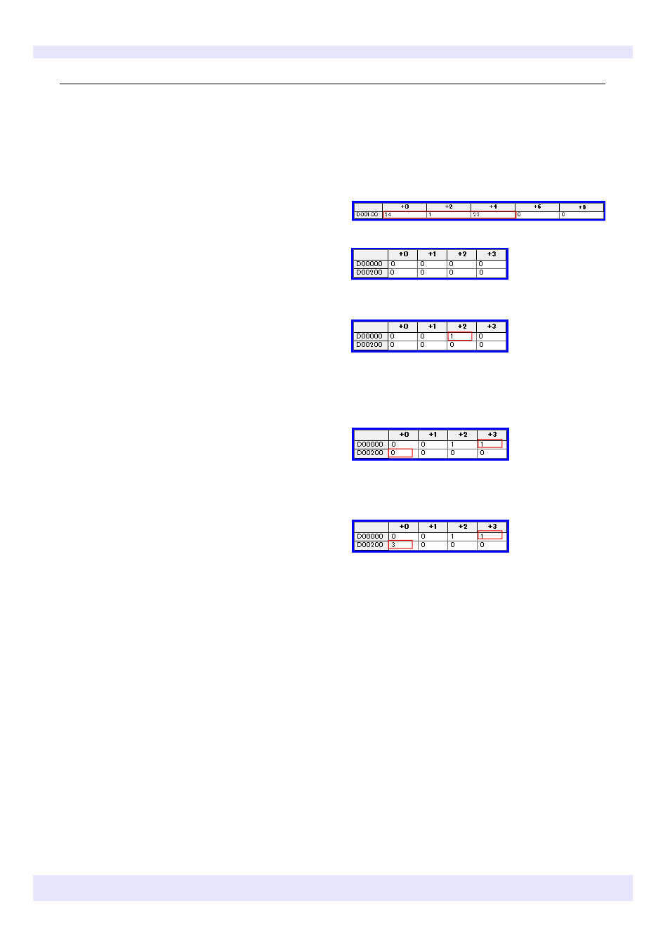
Check the PW (Switch Program Setting No.) command operation.
1. Enter "24", the PW command No., in the data memory
corresponding to the PLC Command Address (D100 in
this example), and the parameters switch target SD drive
No. and program No.
The figure on the right shows an example of switching to
program number "23" on "SD1".
* The address to use is 1 word for Command No. and 2
words for other parameters.
2. Enter 1 in the data memory corresponding to the PLC
Command Execution Address (bit) (D002 in this example).
* The address to use is 1 word.
3. The command is executed.
4. Check if the values of the data memory corresponding to
the PLC Command Complete Address (bit) and Command
Result Address (D003 and D200 respectively in this example)
have changed.
When the command fails: CV‐X writes "1" into Command Complete
Address (bit), and an error code into Command Result Address.
Set the command parameter in 2 word display mode.
Set other settings in 1 word display mode.