KEYENCE CV-X Series User Manual
Page 7
KEYENCE CORPORATION. Vision System Division
‐ 7 ‐
www.keyence.com
6
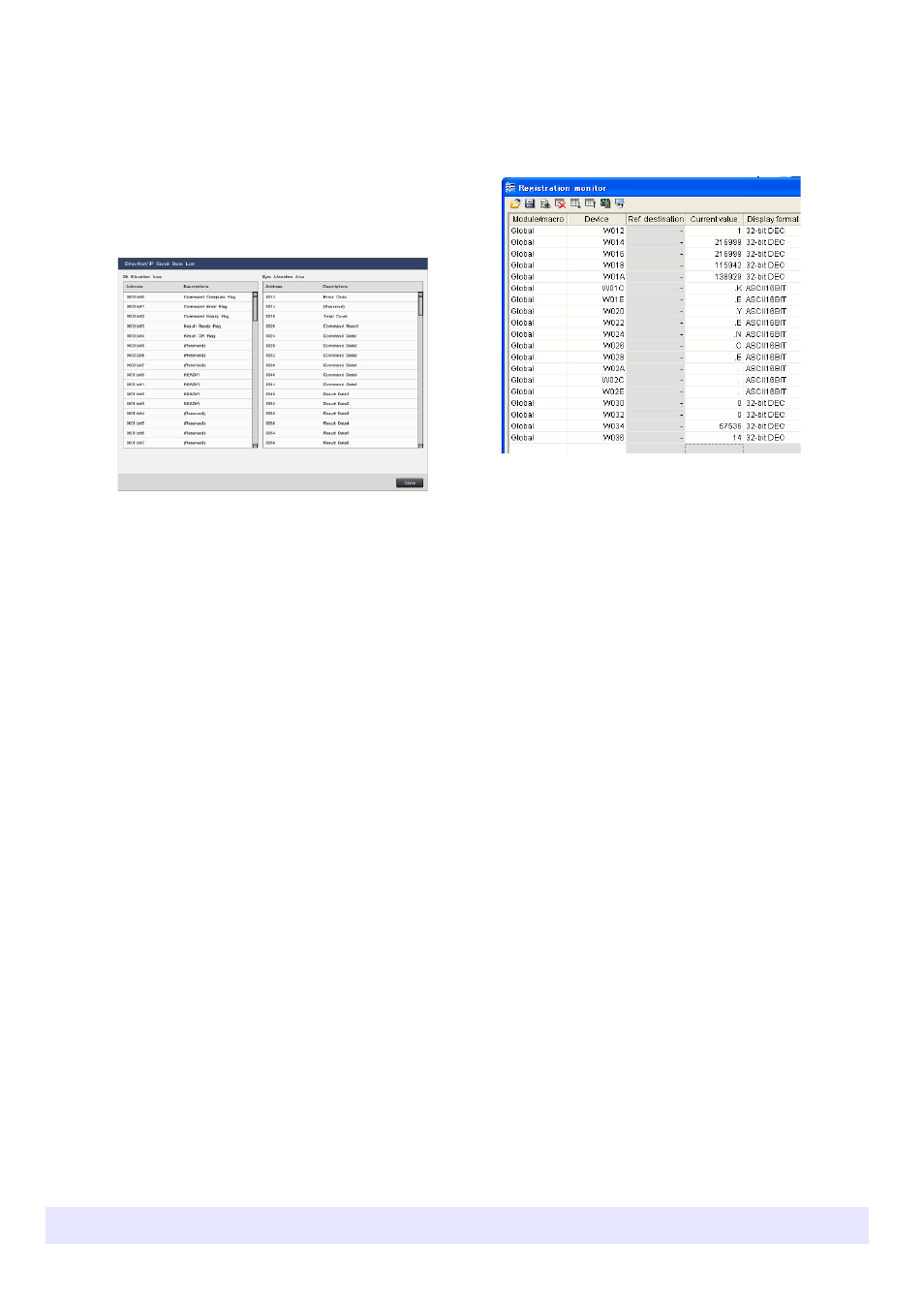
Input the trigger to the CV-X100 Series, then check
the output results in the KV STUDIO registration
monitor.
Check the current value beginning with device W012.
3
From "Global", select "Communications & I/O" -
"EtherNet/IP", and left-click "Set" in "Data
Settings".
The "EtherNet/IP Communication Data Structure"
screen appears.
4
Left-click "View List" in "Send-Data".
The contents that are allocated to the controller send
•By default, "Result Data1" (first result output) is
set for byte address 0048, and the result data is
allocated there.
•As result data is output in 32‐bit units, 4‐byte
addresses are used for each piece of result data
(1 character in the case of text).
5
Restart the controller.
•Judged value OK=0, NG=1 is stored using 2 words.
•Decimal fraction data is multiplied by 1000 and
stored using 2 words: 124.121 → 124121
•When XY data is output, it is stored in order XY
using 2 words each.
•Integer data is stored unchanged using 2 words
•Text data is stored in ASCII code using 2 words
per character
‐ When outputting with "String", the number of
devices used varies depending on the set
character string. In this example, because the
OCR unit "Detected String" is output, the character
string is "KEYENCE" (7 characters). However
because 10 is set for "Characters" in "Block Set",
the 20 words (for 10 characters) from W042 to
W054 are used.
‐ When the characters setting is changed, the device
used changes. If there is a possibility that it might
be changed, it is recommended that it be set at
the end of the output data.
•Judged value OK=0, NG=1 is stored using 2 words.
•System variable: Integer type: Stored using 2 words
as is
Decimal type: Multiplied by 1,000 and stored using
2 words