Outputting the measured value/judged value, Ethernet/ip) – KEYENCE CV-X Series User Manual
Page 6
KEYENCE CORPORATION. Vision System Division
‐ 6 ‐
www.keyence.com
2. Outputting the Measured Value/Judged Value
(EtherNet/IP)
[Keyence KV Series]
1. Setting the output data (Output Settings)
2. Checking the format for output to the byte
address, and the relationship between the byte
address and the link register (W)
Use the output settings to output the measured values
and judged values. This section explains how to
allocate the measured/judged values below as an
example.
•Total Status Value
•T100: Position Adjustment with Shading Pattern
(position X)
•T100: Position Adjustment with Shading Pattern
(position XY)
•T101: Area
•T102: OCR (Recognize Strings)
•T100: Position Adjustment with Shading Pattern
(tool judgment value)
•T101: Area (tool judgment value)
•Program Time
•Date & Time
1
Check an example of result data stored to the
byte address.
The EtherNet/IP output settings are set so that the
result data shown below is output.
•Total Status Value
•T100: Position Adjustment with Shading Pattern
(position X)
•T100: Position Adjustment with Shading Pattern
(position XY)
•T101: Area
•T102: OCR (Recognize Strings)
•T100: Position Adjustment with Shading Pattern
(tool judgment value)
•T101: Area (tool judgment value)
•Program Time
•Date & Time
Outputting the Measured Value/Judged
3
Left-click "Select Data", select the items to output,
and then left-click "Add".
4
Check the byte address for output.
•When allocating output data, the destination byte
address is automatically displayed in "Address".
•The byte address starting position is the position
allocated to "Result Data1" on the "Data
Configurations" ‐ "Send‐Data" ‐ "View List" screen.
(In the example above, it is byte address 048.)
1
From the "Output Settings" screen, left-click
"EtherNet/IP".
The EtherNet/IP output settings screen appears.
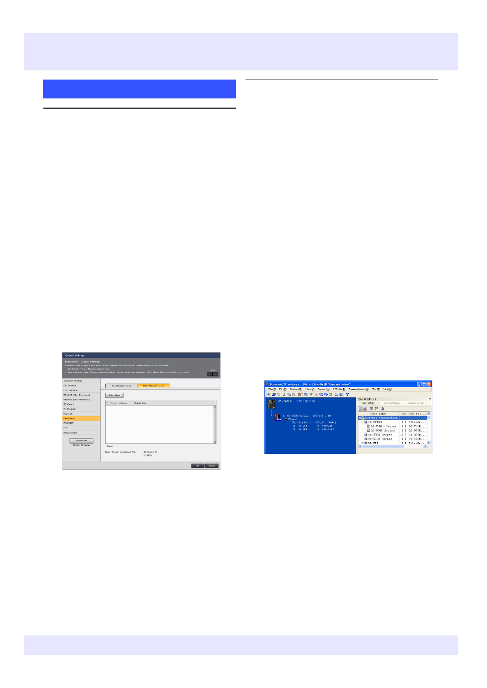
2
Left-click the "Byte Allocation Area" tab.
2
Check the relationship between the byte address
and the link register (W) in KV STUDIO.
Open "EtherNet/IP settings" from the "Setup unit (2)"
tab in KV STUDIO Unit Editor, and click the plus sign
(+) next to "Class1" for the registered CV‐X100 to
check the allocation status of the device. (In the
notation, output from CV‐X100 is treated as "IN
(input)".)
•Check the range (hexadecimal) of the link relay
(B)/link register (W) allocated to the registered
CV‐X100 Series controller. (The range can also be
changed as desired by clicking "Edit".)
•Byte addresses 0000‐0011 are for the link relay
(from B0000 onwards), and byte addresses from
0012 onwards are for the link register. Allocation
begins at the start from W0000, with 1 register
used for each 2‐byte address.