Installing the controller unit, Caution on direction of controller mounting, Installing the expansion unit – KEYENCE XG-8000 Series User Manual
Page 4
4
Install the controller unit to DIN rail, or use the holes on the bottom of
the controller to secure it with screws.
• Do not install the XG in a location with lots of dust or water vapor. The XG
does not have a mechanism to protect the XG from dust or water. Dust or
water entering the controller can cause damage to the XG.
• Turn off the power to the controller when connecting or removing an
expansion unit, a cable, or a terminal block. Connecting or removing the
camera expansion unit, the cable, or the terminal block while the power is
being supplied may damage the controller or peripheral devices.
• When an expansion unit is not connected, place the connector protection
cover back on the controller. Using the controller with the connector
exposed may cause damage to the controller.
Caution on Direction of Controller Mounting
• Install the controller in the direction indicated by the circle as
shown below. Do not install the controller in any other direction.
• For ventilation, keep the space free of objects for 50 mm or more
above the controller and 50 mm or more for both sides. Keep the
space free of objects for 90 mm or more in the front of the
connector panel to connect the cables safely.
• When two or more controllers are installed side by side, keep the
space free of objects for 50 mm or more between controllers, and
50 mm or more on top of both controllers.
• Do not block the ventilation openings on the top and bottom of the
controller. If the vents are blocked, heat is accumulated inside the machine
and can cause system failure.
• If the temperature inside the control panel (temperature at the upper part of
the front surface of the controller) exceeds the rating, use forced air-cooling
or increase the free space around the system to improve ventilation until the
operating ambient temperature drops below the rating.
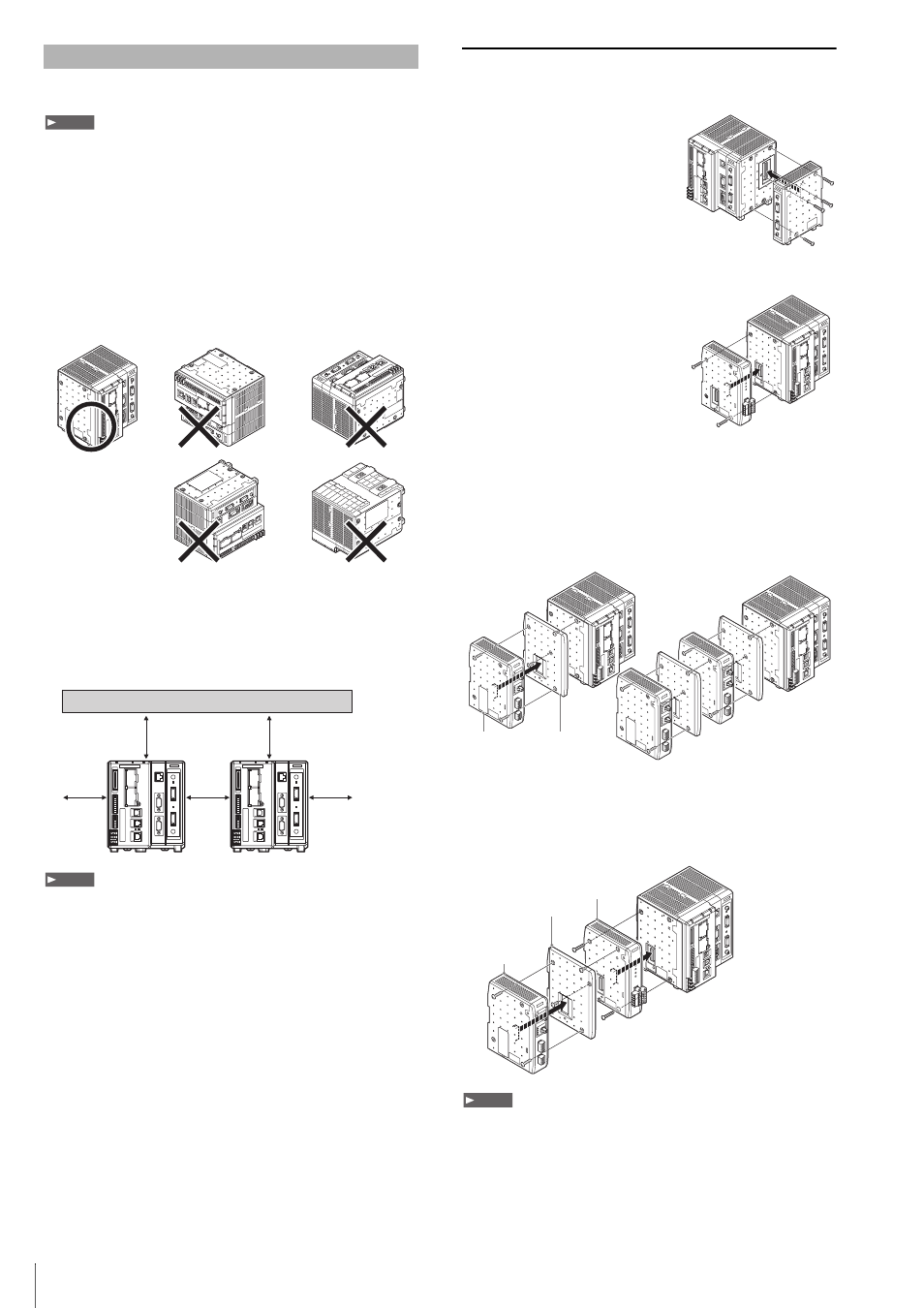
Installing the Expansion Unit
Installing the Camera Expansion Unit
(Excluding the XG-8800(P)/8802(P)/8800L(P)/8802L(P))
When connecting three or more
cameras, after connecting the optional
Camera Input Unit to the optional
Camera Expansion Unit CA-E800/
XG-E800, install to the controller.
After detaching the protection sticker
of connector 1 to the right side of the
main controller, install the Camera
Expansion Unit.
Installing the Communication Expansion Unit
The optional CC-Link expansion unit
CA-NCL10E is used when
communicating with CC-Link devices.
Remove the protective cover of
connector 2 from the left side of the
controller and install the CC-Link
expansion unit.
Installing the Illumination Expansion Unit
A combination of up to 4 CA-DC21E and CA-DC30E illumination
expansion units (sold separately) may be connected for control of up
to 8 individual lighting units. However, a maximum of 2 CA-DC30E
units may be connected for control of up to 4 individual lighting units.
Remove the protective cover of connector 2 from the left side of the
controller and install the illumination expansion unit as shown below.
When using the illumination expansion unit and CC-Link unit
simultaneously
Mount the CC-Link unit CA-NCL10E directly to the controller, then
mount the illumination expansion unit to the left side of the CC-Link
unit.
• Turn off the power to the controller when connecting or removing each
expansion unit. Connecting or removing the each expansion unit while the
power is being supplied may damage the controller or peripheral devices.
• When an expansion unit is not connected, place the connector protection
cover back on the controller. Using the controller with the connector
exposed may cause damage to the controller.
• It is necessary to mount the supplied attachments before mounting the
illumination expansion unit.
Installing the Controller Unit
Note
50 mm
50 mm
50 mm
50 mm
50 mm
Note
When connecting
multiple units
OUT
IN
PO
WER
LIGHT 2
4
3
2
1
LIGHT 1
4
3
2
1
OUT
IN
PO
WER
LIGHT 2
4
3
2
1
LIGHT 1
4
3
2
1
Attachment
(Supplied to
the illumination expansion unit)
Illumination
expansion unit
OUT
IN
PO
WER
LIGHT 2
4
3
2
1
LIGHT 1
4
3
2
1
OUT
IN
PO
WER
LIGHT 2
4
3
2
1
LIGHT 1
4
3
2
1
Attachment (Supplied to
the illumination expansion unit)
Illumination
expansion unit
CC-Link unit
CA-NCL 10E
Note