2 connection and installation, Installing the nozzle/tube, Installing the sj-m series – KEYENCE SJ-M200 User Manual
Page 7: Connecting cables, Connection and installation
6
2-2
Connection and Installation
This section describes how to connect and install the Static Elimination Head and Controller Unit.
Installing the nozzle/tube
Install the nozzle and the tube to the Static Elimination Head by following the procedures below.
It is recommended that this installation be done prior to "Installing the Static
Elimination Head" in the next section. If not, it may become difficult to install the
Static Elimination Head.
■ Installing the nozzle
Attach the nozzle to SJ-M020(G). Attach and tighten
the nozzle mounting fixture to the nozzle to fasten it in place.
■ Installing the tube
An air tube is applicable to SJ-MS3/4 and SJ-ML3/4. Use
an air tube of OP-75350 (PFA tube 500 mm). Static
elimination power varies depending on the length of the
air tube. Check the length carefully before use.
Before using SJ-MS3/4 or SJ-ML3/4 with an air tube mounted, make the "Tube
Installation Setting" in page 8 effective.
CAUTION
Model name
Fastening torque
Between nozzle and nozzle
mounting fixture
2 N·m or less
SJ-MS2/ML2
(between head and adapter)
2–3 N·m or less
SJ-MS3/ML3
(between head and adapter)
7 N·m or less
SJ-MS4/ML4
(between head and adapter)
7 N·m or less
SJ-MS1/ML1
(between resin head and
adapter)
Fasten manually until it stops.
Then use a tool such as
wrench and rotate approx. 2 or
3 times to fasten more. Fix in
your desired direction. If you
fasten a screw too tightly, a
screw section may result in
breakage. Insufficient
fastening may result in
looseness or leakage.
Nozzle mounting fixture
CAUTION
2-2
Connection and Installation
Installing the SJ-M Series
Install the SJ-M Series at locations where static electricity is generated or is likely to be generated.
■ Installing the Static Elimination Head
There are two ways of installing the Static Elimination Head, with or without the mounting fixtures.
When installing the SJ-M Series, observe the minimum bending radius of all
provided cables. Also, do not install the SJ-M Series with the cables deformed
by staples or other objects. Doing so might cause the SJ-M Series to
malfunction.
●
When the mounting fixture is used:
When installing the SJ-M010/020(G), prepare tapped
mounting holes, and install the SJ-M010/020(G) with
M3 screws at a tightening torque of 1 Nm or less (M4
screws: 1 Nm or less).
The M3 screws and bundling band for fastening the
mounting fixture must be prepared separately.
●
When the mounting fixture is not used:
When mounting the SJ-M010/020(G) using the M3 set
screws, tighten at a torque of 0.1 Nm or less.
Install within the allowable mounting fixture range indicated in the external
dimension drawings. Otherwise, static may not be eliminated properly.
CAUTION
M3 tap
M4 tap
M3 tap
M4 tap
•SJ-M010
•SJ-M020 (G)
Install the mounting fixture within the
allowable mounting fixture range
indicated in the external dimension
drawings. Otherwise, static may not be
eliminated properly.
Make a space of 30 mm or more
around the drive unit. Otherwise,
the unit may be damaged.
Important
CAUTION
M3 set screw (flat)
28 mm or more
Limit the tightening torque to
0.1 Nm. Exceeding this torque
might damage the set screws.
CAUTION
Important
2-2
Connection and Installation
■ Installing the discharge prevention cap (option)
An optional discharge prevention cap is available to prevent the risk of accidentally touching the Static
Elimination Head and causing discharge during maintenance work, for example. Use this cap if
necessary.
■ Installing the cap
Install the discharge prevention cap as shown in the following figures, and fasten in place using the set
screws (provided).
(Tightening torque: SJ-M010/020(G): 0.04 Nm or less)
■ Installing the Controller unit
Install and fasten in place
so that the end surface of
the cap is at this position.
OP-75354
●
SJ-M010/020(G) (cross-section view)
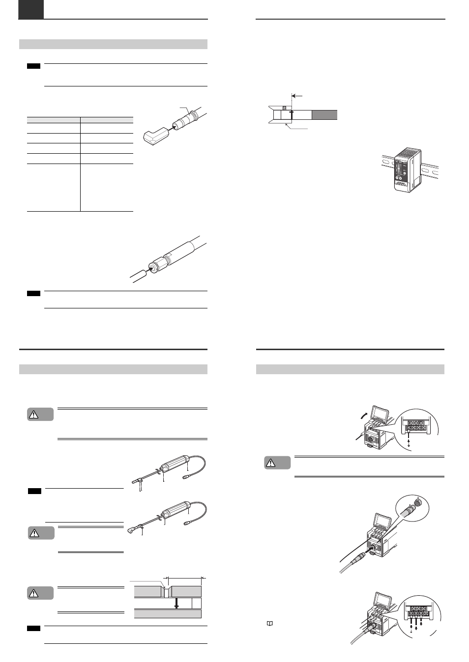
Mount the Controller Unit on the DIN rail.
2-2
Connection and Installation
Connecting Cables
When you have finished installing the Static Elimination Head, connect the earth lead, Static
Elimination Head connector cable and power supply.
■ Connecting the earth lead
Open the terminal plate cover on the Controller
Unit, and connect the earth lead to the GND
connection terminal.
Be sure to connect a Class D earth (maximum
resistance of 100 Ohms).
To prevent electric shock and to ensure accurate static elimination, be sure to
connect a Class D earth (maximum resistance of 100 Ohms).
■ Connecting the cable
Connect the Static Elimination Head
connector cable to the Controller Unit.
Connect this cable with the power
turned OFF.
When installing the Controller Unit
away from the Static Elimination
Head, use the optional extension
cable (SJ-C3).
■ Connecting the power supply
Connect the power supply according to either
of the following methods.
24 VDC power supply
Connect a 24 VDC output power supply
having sufficient power capacity margin to the
power terminals (terminals (5) and (6))
"Controller Unit (I/O terminal section)" (page
3)
Be sure to connect
a Class D earth
(maximum resistance
of 100 Ohms).
WARNING
Match and connect
the end of the connector
cable to the inlet on the
Controller Unit.
To 24 VDC
power supply
To 24 VDC
power supply