Installation precautions – KEYENCE SJ-M200 User Manual
Page 6
5
2-1
Before Installation
Model No. SJ-M020+SJ-MS3/ML3 (500 mm)
Air flow rate 140 Nl/min (pressure
0.3 MPa)
Air flow rate 230 Nl/min (pressure
0.5 MPa)
Model No. SJ-M020+SJ-MS4/ML4 (500 mm)
Air flow rate 145 Nl/min (pressure
0.3 MPa)
Air flow rate 240 Nl/min (pressure
0.5 MPa)
200 150 100 50
0
50 100 150 200
mm
mm
0
200
400
600
100
300
500
800
1000
700
900
3sec
5sec
7sec
200 150 100 50
0
50 100 150 200
mm
mm
0
200
400
600
100
300
500
800
1000
700
900
1100
1300
1500
1200
1400
5sec
7sec
3sec
8sec
2sec
200 150 100 50
0
50 100 150 200
mm
mm
0
200
400
600
100
300
500
800
1000
700
900
7sec
10sec
13sec
200 150 100 50
0
50 100 150 200
mm
mm
0
200
400
600
100
300
500
800
1000
700
900
1100
1300
1500
1200
1400
5sec
10sec
15sec
2-1
Before Installation
Model No. SJ-M020+SJ-ML
Air flow rate 20 Nl/min
(pressure 0.02 MPa)
Air flow rate 60 Nl/min
(pressure 0.1 MPa)
Air flow rate 250 Nl/min (pressure
0.5 MPa)
200 150 100 50
0
50 100 150 200
mm
mm
0
200
400
600
100
300
500
3sec
10sec
15sec
20sec
200 150 100 50
0
50 100 150 200
mm
mm
0
200
400
600
100
300
500
800
1000
700
900
1sec
5sec
10sec
2sec
200 150 100 50
0
50 100 150 200
mm
mm
0
200
400
600
100
300
500
800
1000
700
900
1100
1300
1500
1200
1400
0.5sec
1sec
2sec
2-1
Before Installation
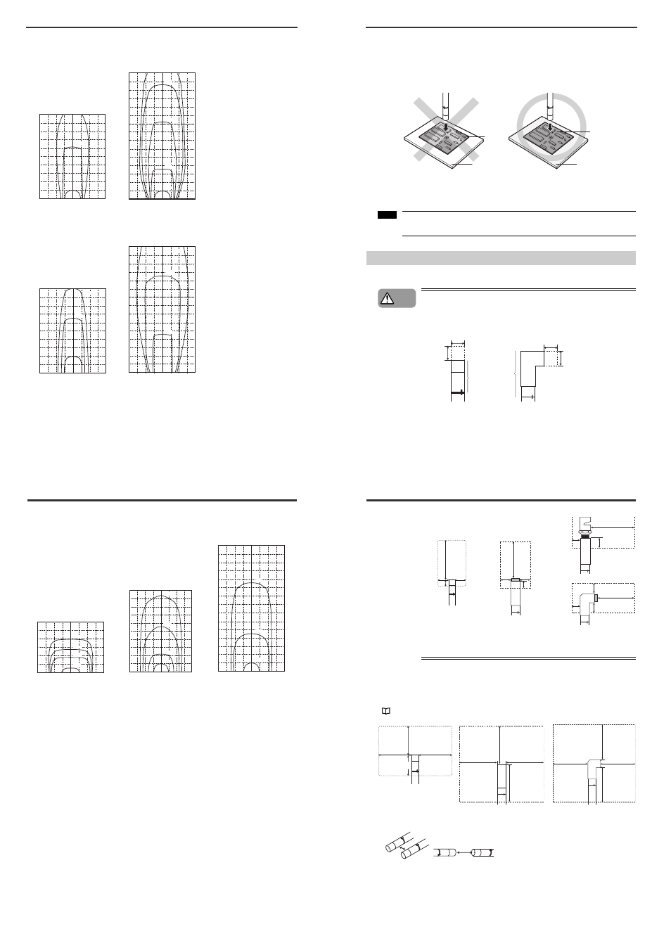
■ Appropriate static elimination method
Pay attention to the following points to ensure that static elimination is performed appropriately.
Static elimination cannot be performed accurately at locations where the target object is
touching a metallic body (earthed body).
Eliminate static from the target object at locations where it is not directly touching metallic bodied
(earthed body).
Static will be eliminated from only the surface of the insulated body (board, etc.) that is facing
the Static Elimination Head.
When eliminating static from both sides of a target object, install two SJ-M Series as one SJ-M Series
must be installed on either side of the target object.
Install the Static Elimination Head so that it can be easily accessed, for example, for
replacement of parts and cleaning.
Installation Precautions
■ Installation site
Install the tip of the SJ-M010/020(G) paying attention to the following point.
• Install the Static Elimination Head away from the wall or surrounding
objects.
• Protect the area around the tip of the Static Elimination Head with silicon,
fluoro-resin or other highly ozone-resistant resin. Ozone that is generated may
cause the metal or resin on the SJ-M010/020(G) to rust, corrode or deteriorate.
Insulating mat
Metal
Board
Board
Note
CAUTION
The section marked by "*" must not touch the conductor (earthed body).
The adapter nozzle must not touch the conductor (earthed body).
23mm*
10 mm or more
10 mm
or more
10 mm or more
10 mm
or more
Requires 10 mm or more away
from the air outlet
*
●
SJ-M010/020(G)
2-1
Before Installation
• Do not install the Static Elimination Head at locations where moving parts of
other equipment and machinery may place stress on the cable. Doing so
might cause the SJ-M010/020(G) Series to malfunction.
■ Interference
The Static Elimination Head may not function properly if there is a conductor (earthed body) located
nearby or if two or more units are used close to each other. In such an installation, refer to the figure
below and maintain the indicated distance between the conductor (earthed body). If a conductor (earthed
body) is located inside the distances indicated below, adjust using the ion balance manual setup.
"Ion Balance Adjustment Function" (page 8)
When two SJ-M Series units are used, refer to the figures below, and install the units so that the
following distances are maintained between the two Static Elimination Heads.
200 mm
or more
20 mm
or more
10 mm
or more
20 mm
or more
20 mm or more
10 mm
or more
200 mm or more
10 mm
or more
20 mm or more
20 mm or more
200 mm or more
When SJ-MS2
is used
When SJ-ML1
is used
When SJ-MS1
is used
200 mm
or more
20 mm
or more
10 mm
or more
20 mm
or more
●
SJ-M010/020 (G)
60 mm or more
away from the
nozzle or air outlet
60 mm or more
60 mm or more
60 mm
or more
60 mm or
more away
from the
nozzle or
air outlet
60 mm or more
60 mm or more
60 mm
or more
●
SJ-M010/020 (G)
60mm or more
60mm
or more
60mm
or more
35mm or more
●
SJ-MS*
●
SJ-ML*
60 mm or more
60 mm or more