Error displays and corrective, Error displays and corrective actions – KEYENCE SK-1000 Series User Manual
Page 20
20
E SK-1000 IM
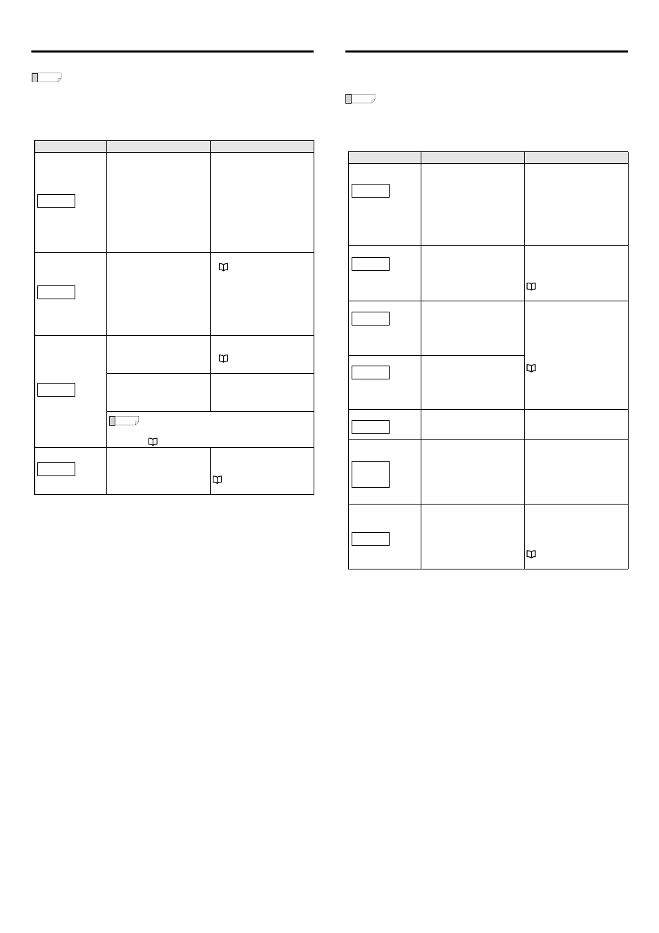
Error Displays and Corrective Actions
When an error occurs, an error message appears on the sensor amplifier.
Reference
•
If an error occurs, the judgment output changes to the error status
and the alarm output turns OFF.
•
When [ErC] is displayed, all judgment outputs and alarm outputs
turn OFF to protect the outputs.
•
When the error display is other than [ErC] or [ErE], the analog
voltage output is 5.5 V and the analog output current is 3.0 mA.
Error displays
Error contents
Corrective actions
Head error
•
The sensor head is not
connected.
•
The head cable is damaged.
•
The sensor head is damaged.
•
A sensor head is connected
that is incompatible with this
amplifier.
•
Check the sensor head
connection.
•
Check whether the head cable
is damaged.
•
Check the connection of the
head cable to the connector.
•
After checking the previous
items, cycle power.
•
Check the models of the
sensor head and sensor
amplifier for compatibility.
Overcurrent error
Overcurrent beyond specification
is flowing through the judgment
output or alarm output.
•
Wire the unit correctly.
•
Check the load and reduce the
current to be within the
specification range.
•
Check that the output wire is
not touching other wires or
ground.
EEPROM error
Reading/writing the nonvolatile
memory (EEPROM) storage has
failed.
•
Cycle power.
•
Perform the initial reset.
Data has been written in the
nonvolatile memory (EEPROM)
over 1 million times and
malfunction occurred.
To save the setting values when
the power is turned OFF, replace
the sensor amplifier.
Reference
When using the zero shift function frequently, make
sure that the zero shift value is not saved in the
nonvolatile memory (EEPROM).
" 12. Zero shift value memory function" (page 16)
Communication error
Communication cannot be
established with the expansion
sensor amplifiers.
Change the settings on the
expansion amplifiers again after
cycling power.
ErH
ErC
ErE
Er.coM
Non-Error Displays and Corrective Actions
When the judgment value (P.V.) is "-----" the judgment outputs turn OFF (When
Normally Open is set), the analog voltage output is 5.5 V and the analog output
current is 3.0 mA.
Reference
If the internal measurement value (R.V.) becomes [-----] because the
target is out of the measurement range, the internal measurement
value (R.V.) retains the value immediately before the target disappears
for the period the response time elapses. After the response time
elapses, the internal measurement value (R.V.) becomes [-----].
Display
Description
Corrective actions
The internal
measurement value
(R.V.) is displayed as
[-----].
The averaging buffer is not full
and the measured value has not
been confirmed.
This occurs when the power is
turned on and immediately after
the head is connected or a reset
is performed. When the amount
of processing specified by the
set averaging rate finishes and
the measured value is confirmed,
this value will be shown on the
measured value display.
The judgment value
(P.V.) is displayed as
[-----].
The hold function is used and the
judgment value (P.V.) has not
been confirmed.
Check the hold function setting.
Input the timing input according
to the setting.
The measurement
value is displayed as
[-ffff].
The measurement value is
smaller than the lower limit of the
display range.
Check the set measurement
range, and if necessary, set it to a
range that corresponds to the
charged state of the target.
The measurement
value is displayed as
[ffff].
The measurement value is larger
than the upper limit of the display
range.
The bank switching method is set
to external input.
To switch the banks with button
operations, set "11. Bank
switching method" to btn.
When R.V. is [-----], [FFFF], or
[-FFFF] - that is, when the value is
too large (a value outside of ±500
V in near mode and a value
outside of ±12.5 kV in far mode)-
the zero shift function has been
used.
Shift the display with the internal
measurement value (R.V.) in the
numeric state (the state in which
the target is measured).
The button operation is disabled.
The connected communication
unit
setting switch is set to RW.
Set the read/write setting switch
to R.
"RS-232C Communication
Unit DL-RS1A User's Manual"
-----
-----
-FFFF
FFFF
bK.Loc
Err
ShiFt
cMLoc