Out 4. dst, Measurement range, Averaging rate – KEYENCE SK-1000 Series User Manual
Page 11: Near far ib, Output state, Distance setting, Deflt usr usr 4. dst 25 u-dst, Usr 4. dst 100 u-dst, Distance setting screen, E sk-1000 im
11
E SK-1000 IM
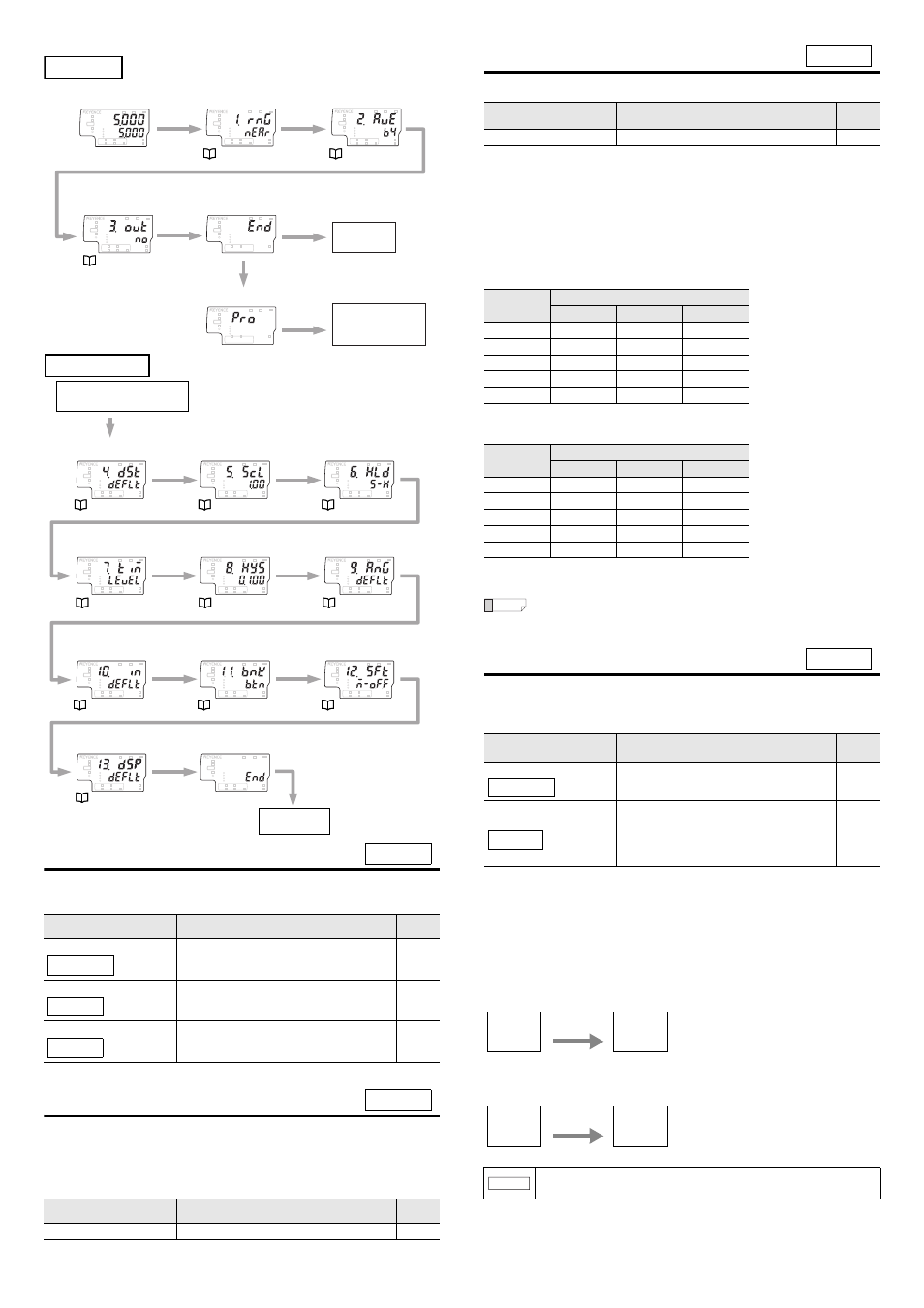
1. Measurement range
You can switch the measurement mode according to the voltage to be measured.
Switch the measurement mode to match the application.
2. Averaging rate
Set the averaging of the data acquired at the sampling rate.
z
Averaging rate
The average value is the moving average. If the measured values fluctuate, stable
measurements can be obtained by increasing the average count.
Measurement range
Description
Default
value
High-precision mode
Measurement can be performed in the range of 0 to
±2 kV and the reference distance for measurement
is 25 mm.
c
Wide-range mode
Measurement can be performed in the range of 0 to
±50 kV and the reference distance for
measurement is 100 mm.
Ion balance mode
The ion balance is measured. The measurement
reference distance is 25 mm.
(* An optional ion balance plate is required.)
Item
Description
Default
value
Averaging rate
1/2/4/8/16/64/256/1024/4096/16384
64
HOLD
HI
V
kV
ALARM
BANK
ZERO SHIFT
TIMING
TEMP
%RH
HI
LO
R.V.
0
1
2
3
LO
GO
HOLD
HI
V
kV
ALARM
BANK
ZERO SHIFT
TIMING
TEMP
%RH
HI
LO
R.V.
0
1
2
3
LO
GO
HOLD
HI
V
kV
ALARM
BANK
ZERO SHIFT
TIMING
TEMP
%RH
HI
LO
R.V.
0
1
2
3
LO
GO
HOLD
HI
V
kV
ALARM
BANK
ZERO SHIFT
TIMING
TEMP
%RH
HI
LO
R.V.
0
1
2
3
LO
GO
HOLD
HI
V
kV
ALARM
BANK
ZERO SHIFT
TIMING
TEMP
%RH
HI
LO
R.V.
0
1
2
3
LO
GO
HOLD
HI
V
kV
ALARM
BANK
ZERO SHIFT
TIMING
TEMP
%RH
HI
LO
R.V.
0
1
2
3
LO
GO
Basic setting
Main screen
1.Measurement
range
2.Averaging
rate
[MODE]
Press for 2
seconds.
[MODE]
or X
[MODE]
or X
[MODE]
or X
Select the advanced
settings
Return to the
main screen.
To the 4. Distance
setting screen
Basic setting
complete
3.Output state
[MODE]
or X
S
or T
[MODE]
or X
HOLD
HI
V
kV
ALARM
BANK
ZERO SHIFT
TIMING
TEMP
%RH
HI
LO
R.V.
0
1
2
3
LO
GO
HOLD
HI
V
kV
ALARM
BANK
ZERO SHIFT
TIMING
TEMP
%RH
HI
LO
R.V.
0
1
2
3
LO
GO
HOLD
HI
V
kV
ALARM
BANK
ZERO SHIFT
TIMING
TEMP
%RH
HI
LO
R.V.
0
1
2
3
LO
GO
HOLD
HI
V
kV
ALARM
BANK
ZERO SHIFT
TIMING
TEMP
%RH
HI
LO
R.V.
0
1
2
3
LO
GO
HOLD
HI
V
kV
ALARM
BANK
ZERO SHIFT
TIMING
TEMP
%RH
HI
LO
R.V.
0
1
2
3
LO
GO
HOLD
HI
V
kV
ALARM
BANK
ZERO SHIFT
TIMING
TEMP
%RH
HI
LO
R.V.
0
1
2
3
LO
GO
HOLD
HI
V
kV
ALARM
BANK
ZERO SHIFT
TIMING
TEMP
%RH
HI
LO
R.V.
0
1
2
3
LO
GO
HOLD
HI
V
kV
ALARM
BANK
ZERO SHIFT
TIMING
TEMP
%RH
HI
LO
R.V.
0
1
2
3
LO
GO
HOLD
HI
V
kV
ALARM
BANK
ZERO SHIFT
TIMING
TEMP
%RH
HI
LO
R.V.
0
1
2
3
LO
GO
HOLD
HI
V
kV
ALARM
BANK
ZERO SHIFT
TIMING
TEMP
%RH
HI
LO
R.V.
0
1
2
3
LO
GO
HOLD
HI
V
kV
ALARM
BANK
ZERO SHIFT
TIMING
TEMP
%RH
HI
LO
R.V.
0
1
2
3
LO
GO
Advanced settings
4.Distance
setting
[MODE]
or X
Advanced setting
complete
[MODE]
or X
5.Area scaling
[MODE]
or X
[MODE]
or X
8.Hysteresis
9.Analog output
scaling
10.External input
11.Bank switching
method
12.Zero shift value
memory function
From the advanced
settings selection screen
[MODE]
or X
[MODE]
or X
[MODE]
or X
[MODE]
or X
[MODE]
or X
[MODE]
or X
[MODE]
or X
7.Timing input
Return to the
main screen.
13.Display digit
[MODE]
or X
6.Hold function
1. rnG
near
far
ib
2. Ave
3. Output state
Set the output state (N.O./N.C.) of judgment output ON/OFF.
There are three judgment outputs:
•
HI judgment output (Black wire)
•
GO judgment output (Gray wire)
•
LO judgment output (White wire)
The judgment output is turned ON/OFF according to the tolerance setting value.
"Changing the Tolerance Values" (page 9)
When Normally Open is set
When Normally Closed is set
*1 "Error Displays and Corrective Actions" (page 20)
*2 When the judgment value (P.V.) is "-----".
Reference
Regardless of the output state setting, the judgment indicator on the sensor
amplifier only matches the judgment output when Normally Open is set.
4. Distance setting
Set the distance correction. When the sensor head cannot be installed at the
reference distance (25 mm for "near" and 100 mm for "far"), you can correct the
measured value by setting the installation distance.
Distance setting screen
When set to the default setting, [defLt], the following screens are skipped.
When you set this to the user setting, [Usr], the distance setting screen is displayed.
z
User setting, [Usr]
•
If the measurement range is [near]
•
If the measurement range is [far]
Item
Description
Default
value
Output state
no
(Normally Open), nC (Normally Closed)
no
Judgment
Judgment output
HI
GO
LO
HI
ON
OFF
OFF
GO
OFF
ON
OFF
LO
OFF
OFF
ON
Error
*1
ON
OFF
ON
"-----"
*2
OFF
OFF
OFF
Judgment
Judgment output
HI
GO
LO
HI
OFF
ON
ON
GO
ON
OFF
ON
LO
ON
ON
OFF
Error
*1
OFF
ON
OFF
"-----"
*2
ON
ON
ON
Distance setting
Description
Default
value
Default setting
The distance will not be corrected.
c
User setting
The distance will be corrected. Set the installation
distance (the setting range).
If the measurement range is "near:" 5 to 50
If the measurement range is "far:" 60 to 120 (unit:
mm)
4.Distance setting
Distance
Press the S and T buttons to specify the
distance. (Setting range: 5 to 50)
4.Distance setting
Distance
Press the S and T buttons to specify the
distance. (Setting range: 60 to 120)
NOTICE
Decreasing the installation distance makes the measurement
range narrower.
3. out
4. dst
defLt
Usr
Usr
4. dst
25
U-dst
X
Usr
4. dst
100
U-dst
X