Basic setting mode, Advanced setting mode – KEYENCE IB Series User Manual
Page 3
3
Basic setting mode
How to enter the Basic setting mode
1. Press the [MODE] button for at least 2 seconds.
2. Press the [MODE] or left/right arrow button and select the function
number.
01 Measurement mode
Set the measurement mode from [% model] and [Dimension mode].
[% mode]: Shows what percentage the received light is, comparing with
the reference light.
[Dimension mode]: Calculates the percentage to dimension.100% is
the width of the laser beam.
(IB-01:1mm/IB-05:5mm/IB-10:10mm/IB-30:30mm)
02 Received/Blocked light mode
Select the mode from [Received Light Mode] and [Blocked Light Mode]
[Received Light Mode]: When the amount of light received by the
Receiver increases, the value increases.
[Blocked Light Mode]: When the amount of light received by the
Receiver decreases, the value increases.
03 Averaging
Set the average number of times. If the average number of times is set
higher, the detection will be more stable.
04 Output mode
Set the output status from [Normally Open] or [Normally Closed].
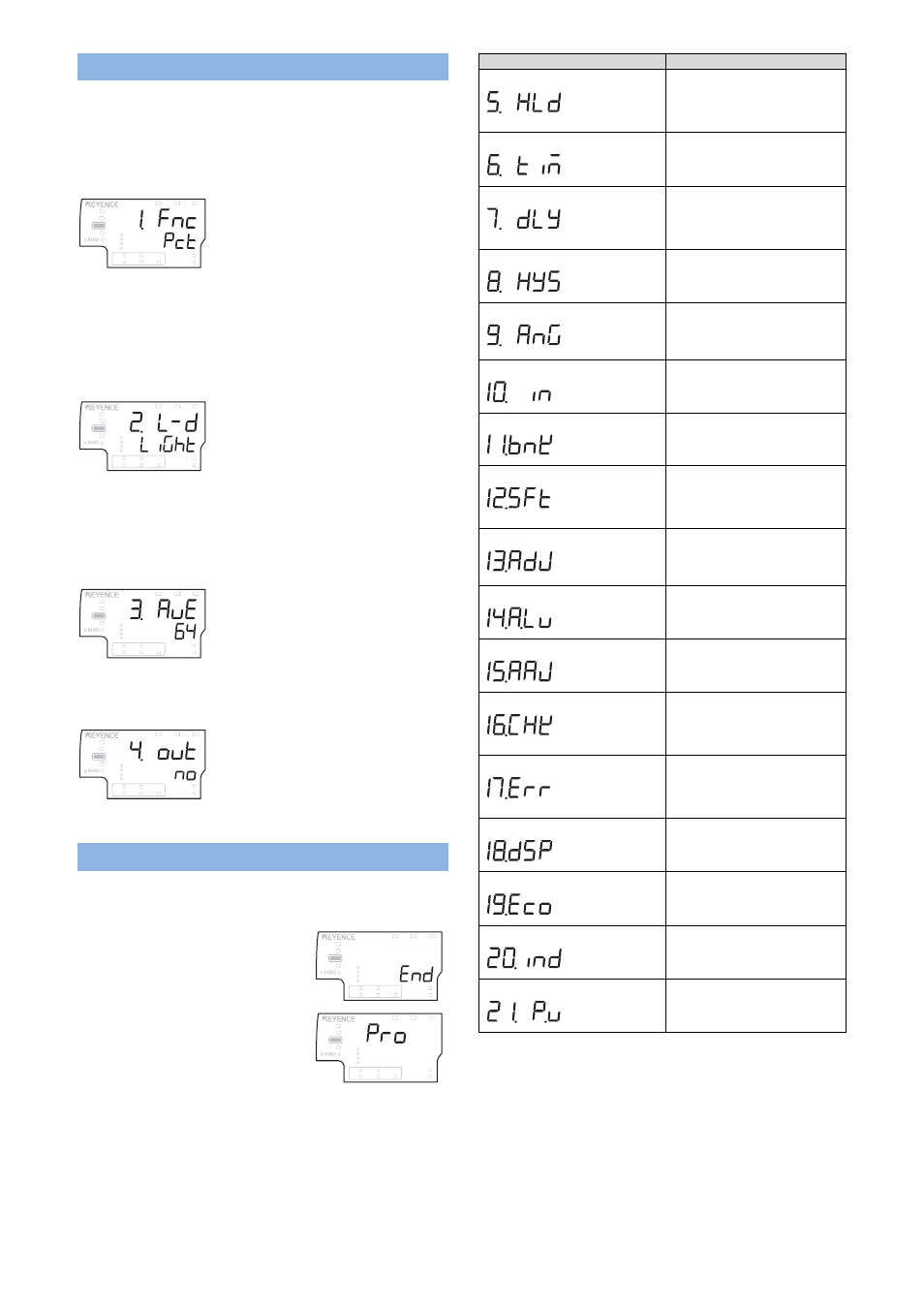
Advanced setting mode
How to enter the Advanced setting mode
1. Press the [MODE] button for at least 2 seconds.
2. Press the [MODE] or left/right arrow
button until the sub display will show
“End”.
3. Press the up/down arrow button. The
main display will show “Pro”.
4. Press the [MODE] or left/right arrow button and select the function
number.
Function
Explanation
05 Hold function
Set how to hold the value from
[Sample], [Peak], [Bottom],
[Peak to peak], [Auto peak]
and [Bottom peak].
06 Timing input
Set how the timing input for the
hold function is used from
[Level] and [Edge].
07 Delay timer
Set the delay timer for the
judgment output from [Off],
[ON-delay], [OFF-delay] and
[1-shot].
08 Hysteresis
Set the hysteresis for the
judgment value.
09 Analog output scaling
Set how the analog voltage or
current should output, related to
the value.
10 External input
Assign each input function to
the 4 external inputs.
11 Bank switching method
Set the way how to switch
banks from [Button] or
[External input].
12 Memorizing the zero shift
Set if the shift target value has
to be memorized to the
EEPROM or not, when the zero
shift was input.
13 Memorizing the adjust input
Set if the adjust input has to be
memorized to the EEPROM or
not.
14 Adjust level
Set the permitted level which
the adjust input can be used.
15 Auto adjust function
Set to use the Auto adjust
function. The adjust input will
be automatically done.
16 Check output function
Set to use the Check output
function. When the received
light is lower than a certain
level, a signal will be output.
17 Error output mode
Set how to output the signal
when an error happens. Select
from normal mode or LX2
compatible mode.
18 Display digit
et the number of digits from
[Default], [0.001], [0.01], [0.1]
and [1].
19 Power saving
Set to use the power saving
function.
20 Judgment indicator color
Set the lighting conditions for
the light on the sensor head.
21 Display color
Set the color of the main
display. (IB-1500/1550)
LASER
BANK
0
1
2
3
HI
LO
R.V.
ANALOG
HI
SHIFT
ZERO SHIFT
TIMING
LO
GO
HOLD
CALC
CHECK
LASER
BANK
0
1
2
3
HI
LO
R.V.
ANALOG
HI
SHIFT
ZERO SHIFT
TIMING
LO
GO
HOLD
CALC
CHECK
LASER
BANK
0
1
2
3
HI
LO
R.V.
ANALOG
HI
SHIFT
ZERO SHIFT
TIMING
LO
GO
HOLD
CALC
CHECK
LASER
BANK
0
1
2
3
HI
LO
R.V.
ANALOG
HI
SHIFT
ZERO SHIFT
TIMING
LO
GO
HOLD
CALC
CHECK
1114-1
LASER
BANK
0
1
2
3
HI
LO
R.V.
ANALOG
HI
SHIFT
ZERO SHIFT
TIMING
LO
GO
HOLD
CALC
CHECK
LASER
BANK
0
1
2
3
HI
LO
R.V.
ANALOG
HI
SHIFT
ZERO SHIFT
TIMING
LO
GO
HOLD
CALC
CHECK