Selecting mode (power/timer), Mutual interference suppression function, I/o circuit – KEYENCE FS-10 User Manual
Page 3: Mounting main unit, Mounting expansion units, Mounting a unit laterally, Detaching units from din rail, Power selection, Timer selection
3
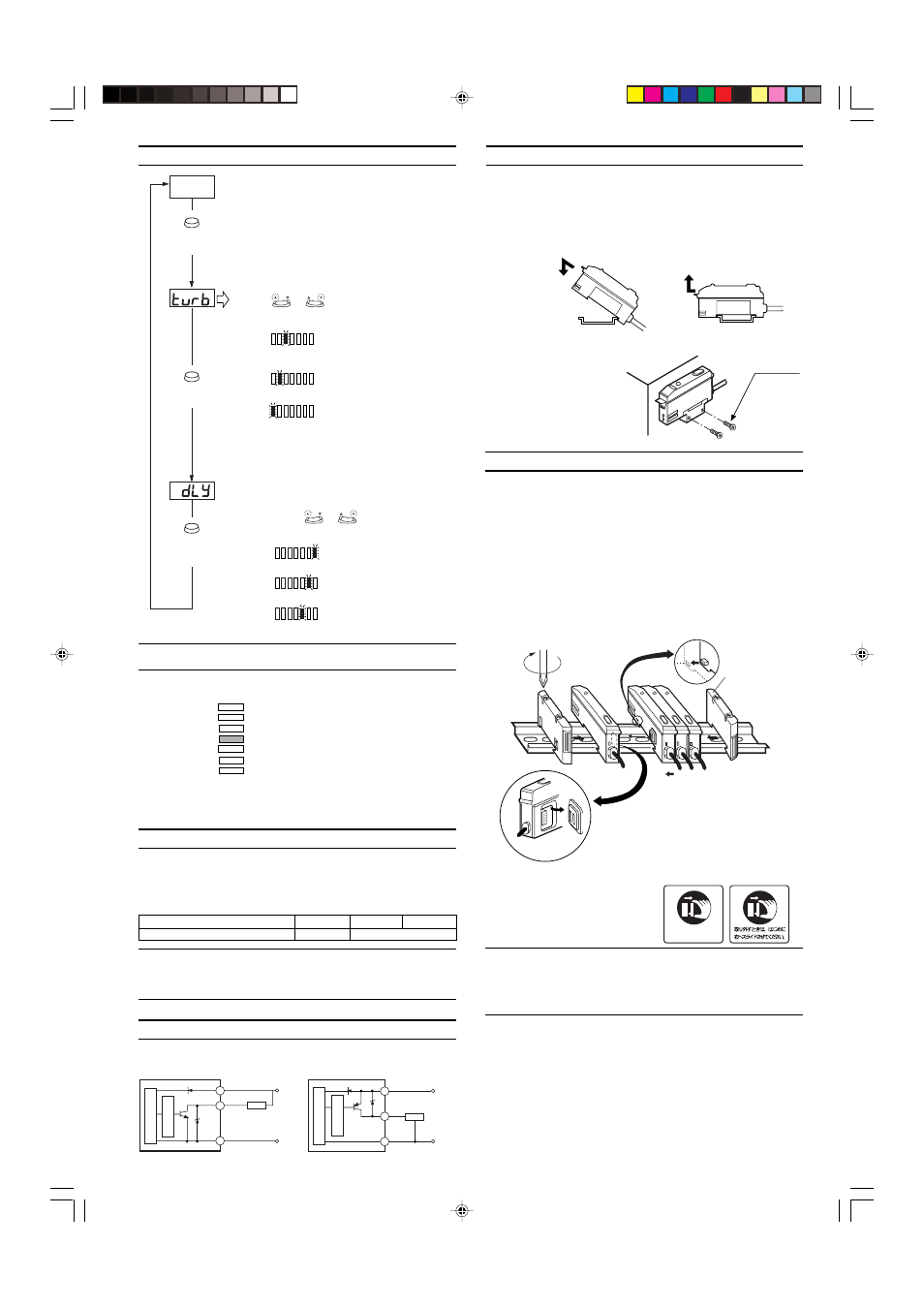
MOUNTING MAIN UNIT
■ Mounting/Detaching the unit to/from a DIN rail or the
mounting bracket.
Hook the claw located at the unit cable side onto the DIN rail, and then
hook the front side claw to the rail while pressing the amplifier forward.
To detach the unit, unhook the front claw by lifting the unit front side
while pressing it forward.
Mounting
Detaching
■ Mounting a unit laterally
Secure the unit with screws
through the side holes of the
supplied mounting bracket
[FS-V11(P) only].
MOUNTING EXPANSION UNITS
■ Mounting expansion units
1. Detach the protective cover from the unit’s side panel.
2. Mount units to a DIN rail one by one.
3. Slide one expansion unit toward another. Align the front claws of the
units and push the unit together until they click.
4. Fix the units together by pushing an end unit onto each end. [The
end units are included in the FS-V12(P)]
■ Detaching units from DIN rail
1. Remove the end units.
2. Slide the expansion units apart, and detach them individually.
(Do not detach multiple units connected together with end units.)
The sticker shown on the right is
included in the expansion unit. Apply
this sticker near the sensor.
SELECTING MODE (POWER/TIMER)
MODE
MODE
MODE
Power selection
One lamp in the bar graph LED monitor flashes
to show the currently selected power mode.
Press
or
to choose the desired power
mode.
When detecting a minute
difference in a short detecting
distance
When the detecting distance of
FINE mode is insufficient
When the environment is hostile,
such as dusty
Current
value
Press this button for
3 seconds or more.
Press this
button once.
Press this
button once.
SUPER
TURBO
FINE
SET
40ms
10ms
OFF
SUPER
TURBO
FINE
SET
40ms
10ms
OFF
SUPER
TURBO
FINE
SET
40ms
10ms
OFF
FINE
TURBO
SUPER
Timer selection
One lamp in the bar graph LED monitor flashes
to show the currently selected output timer
mode. Press
or
to choose the
desired timer mode.
Output timer OFF
OFF-delay for 10 ms
OFF-delay for 40 ms
SUPER
TURBO
FINE
SET
40ms
10ms
OFF
SUPER
TURBO
FINE
SET
40ms
10ms
OFF
SUPER
TURBO
FINE
SET
40ms
10ms
OFF
OFF
10ms
40ms
Note: Be sure to readjust the sensitivity after the power mode is
changed.
Bar graph LED monitor in normal operation
The LEDs show the received
light intensity with respect to
the setting value.
The monitor shows the
stability level of the current
detection.
When the detection becomes unstable due to the change in surround-
ing environment or targets, readjust sensitivity.
MUTUAL INTERFERENCE SUPPRESSION FUNCTION
When several expansion units are connected, each fiber unit is free
from light interference from the adjacent fiber units.
The number of fiber units that are free from light interference depends
on the selected power mode.
Note: When units are not connected using the expansion connectors,
the mutual interference suppression function does not work.
The mutual interference suppression function is limited to 4 units even
if only one unit is set to FINE mode.
The light is steadily
received.
The light is irregularly
received.
The light is irregularly
interrupted.
The light is steadily
interrupted.
➞
➞
Power mode
FINE
TURBO
SUPER
No. of units free from interference
4
8
M3 screw
Main unit
Align the claw.
Up to 16 expansion units
can be connected.
Remove the protective cover.
End unit
(Included with
expansion unit)
Expansion
unit
1.
2.
1. The FS-T1/M1/V1 or PS-T1 can be used as
the same unit as well as the FS-V12.
2. FS-T2/M2 or PS-T2 can be used as the
expansion unit as well as the FS-V12.
3. The FS-R0 is used as the main unit for the
FS-V10, FS-T0 and FS-M0.
Slide the unit to the
right to remove it.
+15% or more
+10% or more
+5% or more
Setting value
-5% or less
-10% or less
-15% or less
I/O CIRCUIT
Photoelectric sensor
main circuit
Black
(Control output)
Brown *
Blue *
Load
100mA max.
Overcurrent
protection circuit
0 V
12 to
24 VDC
* FS-V11 only
Note 1: When several units are connected, confirm the ambient temperature.
(See "Specifications" on P. 1.)
Note 2: To connect several units, be sure to use a DIN rail and end units.
Note 3: To mount or detach several units, be sure to turn the power off.
Note 4: Do not remove the protective cover of the expansion connector on the
outmost unit.
NPN
FS-V11/V12
PNP
FS-V11P/V12P
Black
(Control
output)
Brown *
Blue *
100mA max.
* FS-V11P only
to
24 VDC
0 V
Photoelectric sensor
main circuit
Load
Overcurrent
protection circuit