Output switch, Connecting to external devices, Cable types – KEYENCE FS-N10 Series User Manual
Page 4: M8/e-con connector types, M8 connector cable (sold separately), Error displays and corrective actions, Initializing the settings, Initialization method, Initial settings, Using a fiber cutter and cautions for use
4
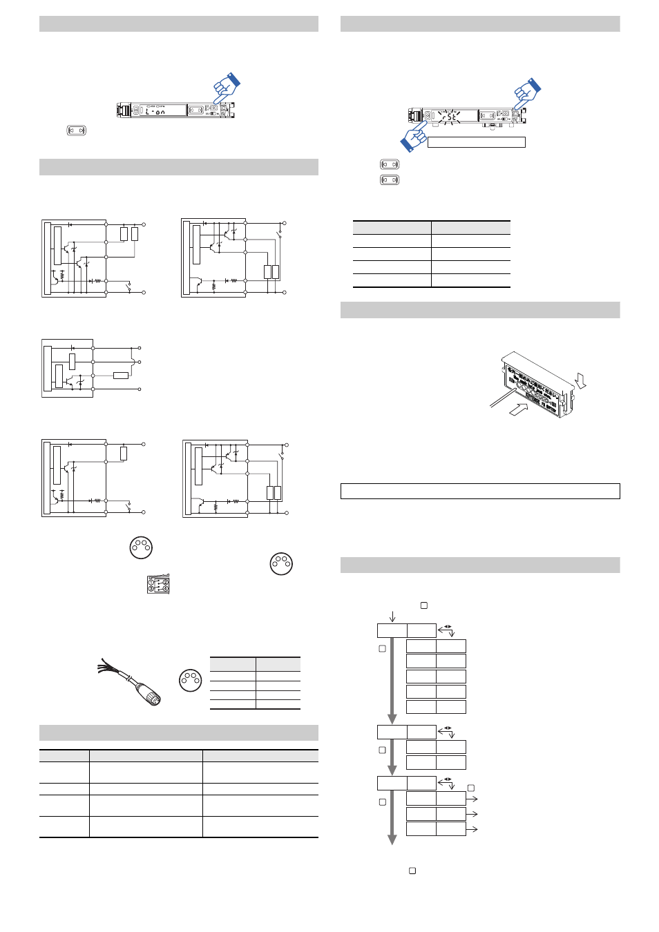
Output Switch
Either light-ON (L-on) mode or dark-ON (D-on) mode can be selected.
1
While the current value is displayed, press the [MODE] button once.
2
Use
to switch the output (
.QP
/
&QP), then press the [MODE] button again.
The output change completes, and the display returns to the current value.
Connecting to External Devices
Cable Types
M8/e-CON Connector Types
M8 connector Cable (Sold Separately)
For FS-N11CN/N11CP/N12CN/N12CP/N13CP/N14CP
Error Displays and Corrective Actions
Consult your nearest KEYENCE office regarding error displays other than the ones listed above.
Initializing the Settings
Initialization Method
1
Press and hold the [SET] and [PRESET] buttons simultaneously for three seconds.
2
Use the
to select "
456", then press the [MODE] button.
3
Use the
to select "
K0K6", then press the [MODE] button.
After initialization is complete, the display returns to the current value.
z
Initial Settings
Using a Fiber Cutter and Cautions for Use
Using a Fiber Cutter
1
Insert the fiber into the cutter hole.
2
Bring down the blade in a single,
swift motion to cut the fiber.
Cautions for Using a Fiber Cutter
•
The fiber cutter comes with the fiber unit.
•
When cutting a fiber unit to be attached to the FS-N10 Series, be sure to use a gray fiber cut-
ter (OP-87098)
•
Stopping the blade midway could cause a bad cut plane, reducing the detection range.
•
Do not use the same hole twice.
Function Configuration
Basic Setting
*1 You can press the
button to set between the range of
2 to 2.
FS-N11N/N12N/N13N/N14N
FS-N11P/N12P/N13P/N14P
*1 FS-N11N/N13N only
*2 FS-N13N/N14N only
*1 FS-N11P/N13P only
*2 FS-N13P/N14P only
FS-N11MN
FS-N11CN/N12CN/N11EN/N12EN
FS-N11CP/N12CP/N13CP/N14CP
*1 FS-N11CN/N11EN only
*1 FS-N11CP/N13CP only
*2 FS-N13CP/N14CP only
*3 FS-N11CP/N12CP only
Error display
Cause
Solution
ErC
Overcurrent in the control output.
Check the load and return the current
within the rated value.
ErE
Failed to write/load the internal data. Perform initialization (p.4).
End APC
Large load on the light source.
Replace the sensor if highly precise
detection is required.
Loc
The keylock function is ON.
For disabling (setting) method, see
"FS-N10 Series User's Manual".
12 to 24 VDC
DC3.3V
Black
(Control output 1)
(Control output 2)
PLC, etc.
White
Pink
*2
*2
Brown
*1
0V
Load
Load
Blue
*1
Sensor main circuit
Overcurrent
protection circuit
(Short-circuit
current 1 mA
or less)
12 to 24 VDC
Black
(Control output 1)
(Control
output 2)
*2
PLC, etc.
White
Pink
*2
Brown
*1
0V
Load
Load
Blue
*1
Sensor main circuit
Overcurrent
protection circuit
(Short-circuit
current 2 mA
or less)
0 V
Brown
Black
Monitor output (1 to 5V)
Orange
Load
Blue
(Control output)
12 to 24 VDC
Device with input
impedance
10 k
Ω or more
Protection
circuit
Sensor main circuit
Overcurrent
protection circuit
*1
*1
DC3.3V
Sensor main circuit
Overcurrent
protection circuit
12 to 24 VDC
PLC, etc.
0V
(Short-circuit
current 1 mA
or less)
PLC, etc.
0V
(Short-circuit
current 1 mA
or less)
(Control output)
Load
*3
*1
*1
Sensor main circuit
Overcurrent
protection circuit
12 to 24 VDC
PLC, etc.
0V
(Short-circuit
current 2 mA
or less)
(Control output 1)
(Control
output 2)
*2
Load
Load
1
2
3
4
M8 connector Pin layout
FS-N11CN/N12CN
e-CON connector Pin layout
FS-N11EN/N12EN
1
2
3
4
M8 connector Pin layout
OP-73864
(Cable length: 2 m)
OP-73865
(Cable length: 10 m)
1
2
3
4
Connected
pin No.
Pin - Pin and wire color table
1
Brown
2
3
4
White
Blue
Black
Wire color
Setting
Initial Value
Power mode
FINE
Detection mode
Std (Normal)
Setting value
50
Output switch
L-on
Failure to follow the cautions below could reduce the detection range.
Press and hold for 3 seconds or more
Fiber
Always insert fiber from the side with writing
Fiber cutter
(OP-87098)
2
1
MODE
Press and hold for 3 seconds or more
HIGH SPEED mode
FINE mode
TURBO mode
SUPER mode
ULTRA mode
MEGA mode
Normal sensitivity setting method
Percentage Calibration*
1
Zero-shift calibration
Settings complete
Go to detection setup mode
Go to display setup mode
Go to system setup mode
MODE
MODE
MODE
MODE
J52
(KPG
6WT$
5W24
7.64
/')#
5V)
5V)
5V)
5'6
5VF
5'V2
15'V
'0&
(W0E
&K52
5;5
5'6
5'6
Return to normal display
MODE