Disable the zero shift function, Output switch, Initializing the settings – KEYENCE PS-N10 Series User Manual
Page 7: Initialization method, Initial settings, Key lock, Activating key lock, Deactivating key lock, Error displays and corrective actions, Connecting to external devices
7
z
Disable the Zero Shift Function
Press and hold the [PRESET] button to disable the zero shift function.
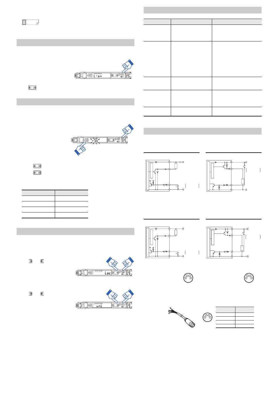
Output Switch
Either light-ON (L-on) mode or dark-ON (D-on) mode can be selected.
1
While the current value is displayed,
press the [MODE] button once.
2
Use
to switch the output (
L-on
/
D-on
), then press the [MODE] button again.
The output change completes, and the display returns to the current value.
Initializing the Settings
Initialization Method
1
Press and hold the [SET] and
[PRESET] buttons simultaneously
for more than three seconds.
2
Use the
to select "
RST
", then press the [MODE] button.
3
Use the
to select "
iNiT
", then press the [MODE] button.
After initialization is complete, the display returns to the current value.
z
Initial Settings
Key Lock
The key lock function disables button operation to prevent unauthorized use.
Activating Key Lock
1
Press and hold the [MODE] button
and
(or
) simultaneously for
three seconds or more.
2
The screen displays "
Loc
", disabling
key operation.
Deactivating Key Lock
1
Press and hold the [MODE] button
and
(or
) simultaneously for
three seconds or more.
2
The screen displays "
unL
", enabling
key operation.
Error Displays and Corrective Actions
For errors other than the above, contact your nearest KEYENCE office.
Connecting to External Devices
Cable Type
M8 Connector Type
Socket Cable (Sold Separately)
For PS-N11Cx / N12Cx
The light intensity may not be set to "
.
0
" when the reflective model sen-
sor head is first installed.
In this case, using the zero shift function to set the state with no target
present to "
.
0
" will make it easier to see the difference in light intensities.
Setting
Initial value
Power mode
TURBO
Detection mode
Std (Normal)
Setting value
50
Output switch
L-on
Reference
SEL
M
Press and hold for 3 seconds or more
SEL
M
SEL
M
SEL
M
Error display
Cause
Solution
ErC
Overcurrent in the control out-
put.
•
Check the load and return the cur-
rent within the rated range.
•
Check that the output wire is not
contacting any other wire or frame.
ErH
Sensor head cable is broken or
is not connected.
•
Check that the sensor head is
connected.
•
Check sensor head cable for dam-
age.
•
Check the sensor head cable con-
nector for damage or loose con-
nections.
After checking, turn the power
OFF and ON.
ErE
Internal data write / load failed.
Turn the power OFF and ON. If the
data is not recovered, initialize the
settings.
Loc
Key lock function is enabled, or
the power mode was fixed to
MEGA mode using the selector
switch.
•
Release the key lock.
•
Check that the sensor amplifier
selector switch is set to MEGA
mode.
The DTM indicator
flashes.
Correction error in DATUM1 or
DATUM 2 mode.
See "PS-N10 Series UserÊs Manual"
for details.
PS-N11N / N12N
PS-N11P / N12P
Input / output circuit diagram
Input / output circuit diagram
*1 PS-N11N only
*1 PS-N11P only
PS-N11CN / N12CN
PS-N11CP / N12CP
Input / output circuit diagram
Input / output circuit diagram
*1 PS-N11CN only
*1 PS-N11CP only
10-30 VDC
3.3 VDC
Black
(Control output)
PLC, etc.
Short-circuit current
1 mA or less
Pink
Brown*
1
Blue*
1
Sensor main circuit
Ov
ercurrent protection circuit
0V
Load
Short-circuit current
2 mA or less
10-30 VDC
PLC, etc.
Pink
Blue*
1
0V
Black
(Control output)
Brown*
1
Sensor main circuit
Ov
ercurrent protection circuit
Load
10-30 VDC
3.3 VDC
(Control output)
PLC, etc.
*1
*1
0V
Short-circuit current
1 mA or less
Sensor main circuit
Ov
ercurrent protection circuit
Load
10-30 VDC
(Control output )
PLC, etc.
Short-circuit current
2 mA or less
0V
Sensor main circuit
Ov
ercurrent protection circuit
Load
1
2
3
4
M8 connector pin layout
1
2
3
4
M8 connector pin layout
OP-73864
(Cable length: 2 m)
OP-73865
(Cable length: 10 m)
1
2
3
4
Connected
pin No.
Pin and wire color table
1
Brown
2
3
4
White
Blue
Black
Wire color