Ps-n10 series quick start, Quick start, Mounting unit – KEYENCE PS-N10 Series User Manual
Page 3: Mounting on a din rail, Installation on a wall (main unit only), Connecting the sensor head to the sensor amplifier, Installing the sensor head connector, Connecting the sensor head
3
PS-N10 Series Quick Start
Quick Start
*1 Not available for 0-line types.
*2 Press and hold the [MODE] button to make advanced setting changes.
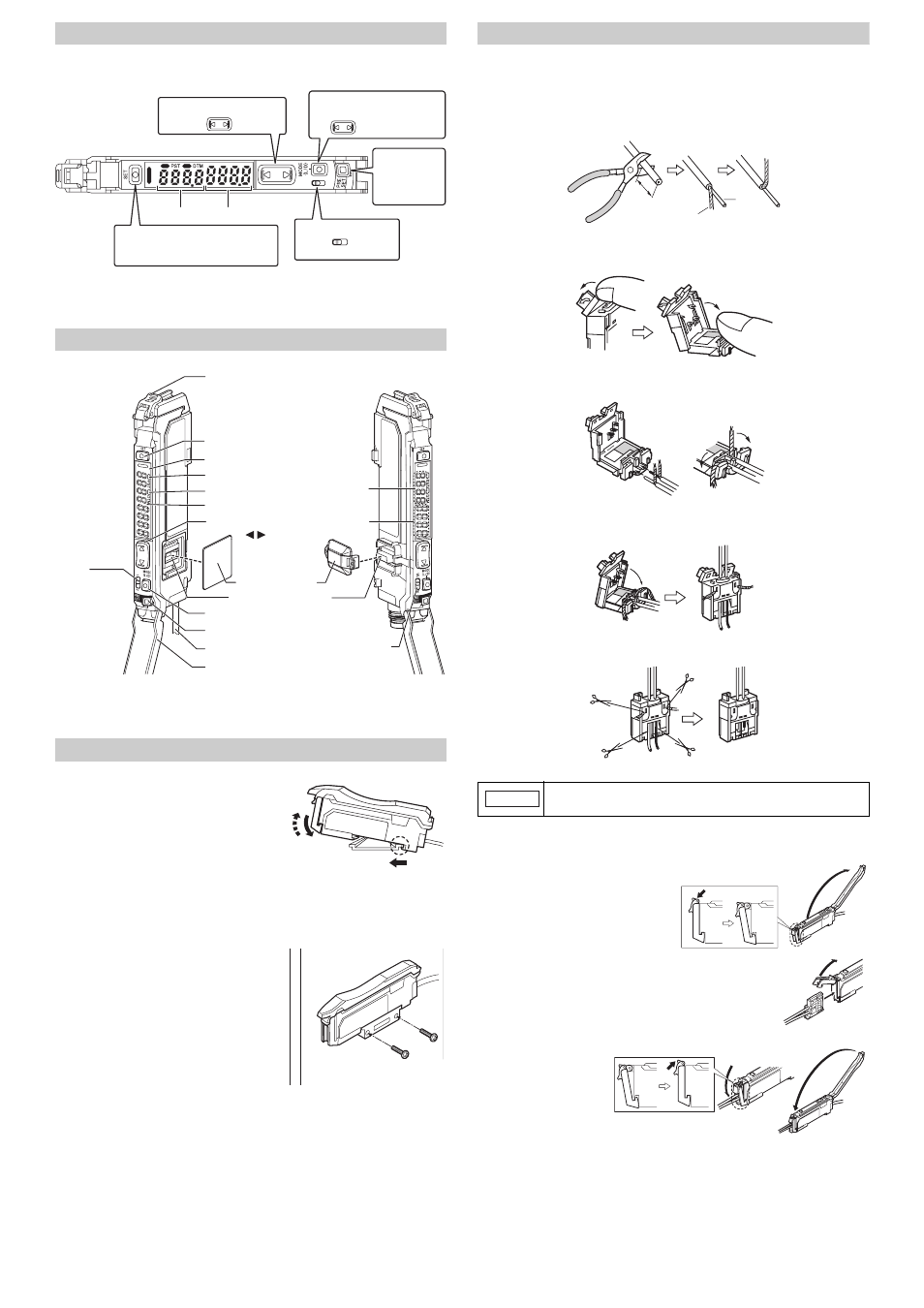
Names of Each Part of the Main Unit and Expansion Unit
* On the PS-N11Cx / N12Cx, this is an M8 connector rather than a cable. Not available for 0-line
types.
Mounting Unit
Mounting on a DIN Rail
1
Align the claw at the bottom of the main body
with the DIN rail, as shown on the right.
While pushing the main body in the direction
of the arrow 1, push down in the direction of
arrow 2.
2
To dismount the sensor, raise the main body
in the direction of the arrow 3 while pushing
the main body in the direction of arrow 1.
Installation on a Wall (Main Unit Only)
1
Attach the unit to the optional mounting
bracket (OP-73880), and secure with two M3
screws as shown on the right.
Connecting the Sensor Head to the Sensor Amplifier
Installing the Sensor Head Connector
1
Process the cable ends as shown below. The core wire conductors are stripped so
that they are exposed at the time of shipment. Be sure to process the cables without
removing the insulation from the cable ends.
2
Move the upper left part of the connector in the direction of the arrow and then open
the connector.
3
Fully insert the cables with the shielded wires standing upright. Next, bend the
shielded wires along the grooves in the direction of the arrow.
4
Close the connector to crimp the cables. Return the upper part of the connector to its
original position and then lock it.
5
Using nippers, cut off the ends of cables protruding from the connector.
Connecting the Sensor Head
1
Open the dust cover, and move the
head lock lever down.
2
Lift the hook up, and insert the connec-
tor completely.
3
Lower the hook to the
position shown in the
drawing, and secure
the head lock lever by
pushing up.
SEL
M
Fine sensitivity adjustment
Mode/Output *
2
Press the [MODE] button once, then
to select L-on or D-on
use
Preset function
Configure easily
with a single press
when receiving light
Down
Up
Power select switch *
1
Standard MEGA (fixed)
Setting value Light intensity
Sensitivity setting
Press once each for workpiece/no workpiece
SEL
M
Power
selection switch
Sub screen
(Displayed in green)
Main screen
(Displayed in red)
Dust cover
Head lock lever
MODE button (MODE)
Power select switch
Cable*
Expansion
protective cover
Expansion connector
Preset button (PRESET)
Manual button
( )
SET button (SET)
Operation status indicators
Digital display
PST indicator
DTM indicator
1
3
2
Crimp the cables no more than three times. Excessively crimping the
cables may result in a bad connection.
10 mm or longer
Shielded wire
Cable
core
Red wire
White wire
NOTICE