Holtgreven Truck Scale Resources User Manual
Page 28
PT300 Users manual
Rev G, Feb 2011
Page 28 of 44
1. Position the corner fixture with rubber pad on the scale position #1. Apply 2500 lbs to the
loading block. Annotate the reading.
2. Repeat for the #2 position.
3. If all readings are within 5 pounds and the previous calibration passed all of the readings
continue with the rest of the calibration verification. If the corner check fails go to the corner
adjust calibration procedure.
Scale Span Calibration
Tools required:
•
Calibration force generator; press or deadweights. This calibration source must cover the
range of 10% to 100% of nominal capacity with an accuracy of 0.25% of reading or better.
PT300
•
100027 - 8" (
±
0.25") x 8" (
±
0.25") x 1.75" (minimum) aluminum loading block.
•
100028-A - 8" (
±
0.25") x 8" (
±
0.25") x 0.5" (
±
0.125") rubber loading scale. (40 to 70 Shore A
rating)
PT300DW
•
100029
- 12" (
±
0.25") x 12" (
±
0.25") x 1.75" (minimum) aluminum loading block.
•
100030-A
- 12" (
±
0.25") x 12" (
±
0.25") x 0.5" (
±
0.125") rubber loading scale. (40 to 70 Shore
A rating)
4. Bring the scales to the calibration site. If there is more than 5
°
F difference in temperature
between the scale temperature and the calibration site allow the scales to reach room
temperature.
5. Place scale on calibration fixture. Turn scale on. Wait 3 minutes for warm-up.
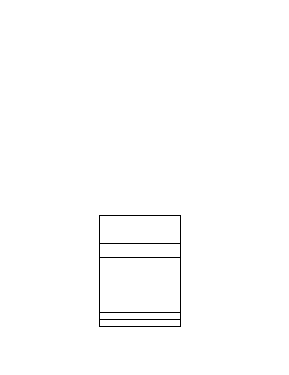
6. Apply test forces every 10% of the scales capacity and verify that the reading falls within 1% of
the applied force or 1 display division whichever is greater as shown in the sample table below.
20K Capacity
Test
force
(lb)
Lower
limit
(lb)
Upper
Limit
(lb)
0
0
0
2000
1980
2020
4000
3960
4040
6000
5940
6060
8000
7920
8080
10000
9900
10100
12000
11880
12120
14000
13860
14140
16000
15840
16160
18000
17820
18180
20000
19800
20200
0
-20
20
7. If any value is out of acceptable limits proceed to the adjust calibration procedure.
8. If all values are within acceptable limits unit passes calibration verification.