Checkline Series-5I User Manual
Page 7
Model 5i Digital Force / Torque Indicator
User’s Guide
6
3.3 Mounting to a plate
The 5i can be mounted to a plate with four thumb screws fastened into the appropriate holes in the rear
half of the housing. Refer to the Dimensions section for detailed hole information and locations.
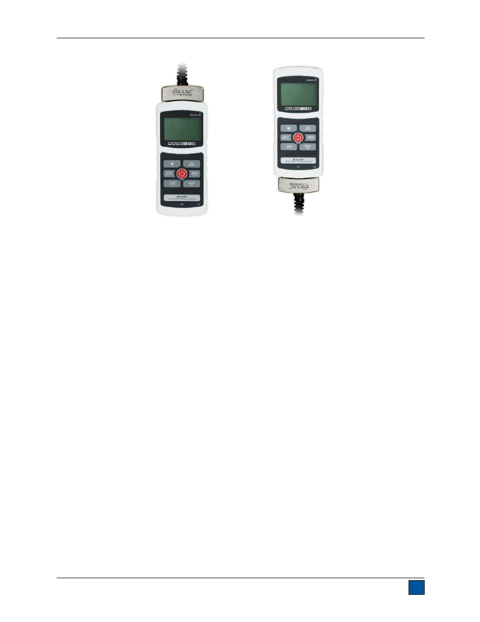
Sensor connector
oriented up
Sensor connector
oriented down
See also other documents in the category Checkline Sensors:
- Series-2 (16 pages)
- Series-3 (22 pages)
- Series-4 (26 pages)
- Series-5 (34 pages)
- FGV-XY (19 pages)
- DS2 (6 pages)
- FGE (8 pages)
- Series-3I (24 pages)
- MG (2 pages)
- FGE-XY (6 pages)
- FB (4 pages)
- ES10 (4 pages)
- FGS-100H (2 pages)
- FGS-250W (2 pages)
- TSB100 (10 pages)
- ES30 (6 pages)
- ES05 (4 pages)
- TSA750 (10 pages)
- TSF (6 pages)
- ESM301 (27 pages)
- MX2 (8 pages)
- FGS-100PV (20 pages)
- FGS-220VC (33 pages)
- MX-500 (4 pages)
- ESMH (6 pages)
- FGS-100PX (20 pages)
- ZP (10 pages)
- WT-100 (2 pages)
- AWS-4050 (14 pages)
- TI-25LT (9 pages)
- TI-25S (11 pages)
- TI-25M (13 pages)
- TI-25DL (19 pages)
- TI-25M-MMX (15 pages)
- TI-25DL-MMX (17 pages)
- TI-007 (9 pages)
- TI-007DL (11 pages)
- TI-CMX (29 pages)
- TI-CMXDL (35 pages)
- TI-CMXDLP (54 pages)
- TI-MVX (42 pages)
- TI-UMX2 (29 pages)
- TI-25P (11 pages)
- TI-44N (11 pages)