Checkline Series-5I User Manual
Page 15
Model 5i Digital Force / Torque Indicator
User’s Guide
14
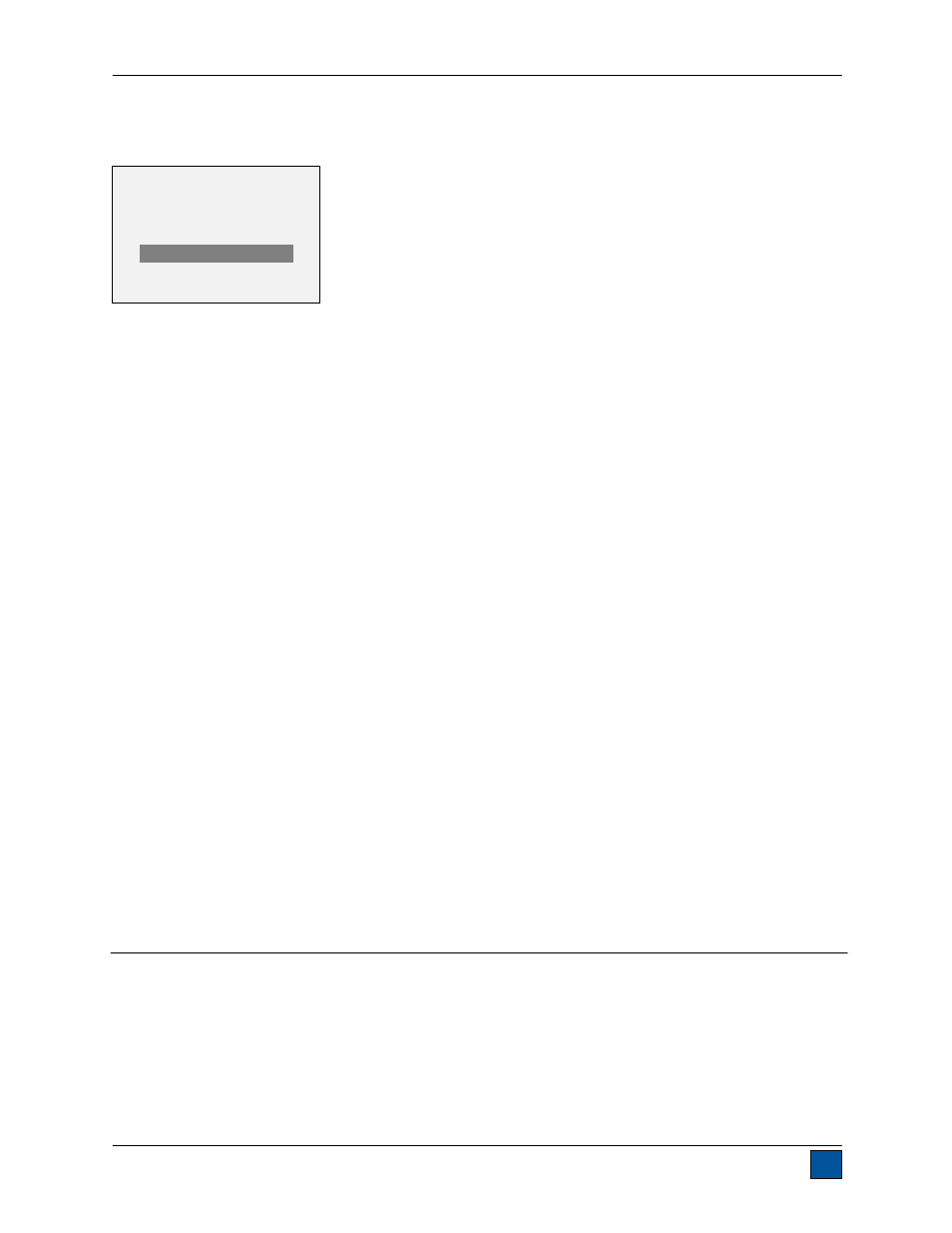
to the desired reading and press DELETE. The letter “D” will appear to the left of the record number,
indicating that the indicator is in Delete mode, as follows:
Press ENTER to delete the value. To exit Delete mode, press DELETE again. Any number of readings
may be individually deleted, however, all readings may also be cleared simultaneously. Refer to the Clear
All Data section for details.
8.2 Statistics
Statistical calculations are performed for the saved values. Calculations include number of readings,
minimum, maximum, mean, and standard deviation.
8.3 Output Data
Press ENTER to output data to an external device. The display will show, “SENDING DATA…”, then
“DATA SENT”. If there was a problem with communication, the display will show, “DATA NOT SENT”.
Saved data can be downloaded by some Mark-10 data collection programs. Refer to their respective
user’s guides for details.
8.4 Output Statistics
Press ENTER to output statistics to an external device. The display will show, “SENDING STATS…”, then
“STATS SENT”. If there was a problem with communication, the display will show, “STATS NOT SENT”.
8.5 Output Data & Stats
Press ENTER to output data and statistics to an external device. The display will show, “SENDING
DATA”, then “SENDING STATS…”, then “DATA SENT”, then “STATS SENT”. If there was a problem with
communication, the display will show, “DATA NOT SENT” and/or “STATS NOT SENT”.
8.6 Clear All Data
Press ENTER to clear all data from the memory. A prompt will be shown, “CLEAR ALL DATA?”. Select
Yes to clear all the data, or No to return to the sub-menu.
For output of data and/or statistics, RS-232 or USB output must be enabled. Data formatting is
output is possible, however, output of statistics is not. Refer to the Communications section for details.
Note: Data is not retained while the indicator is powered off.
9 COMMUNICATIONS
Communication with the 5i indicator is achieved through the micro USB or 15-pin serial ports located at
the bottom of the instrument, as shown in the illustration in the Power section. Communication is possible
only when the indicator is in the main operating screen (i.e. not in a menu or configuration area).
9.1 Installing the USB driver
It is recommended that the USB driver be installed before physically connecting the indicator to
the PC with a USB cable.
0001 8.450 Nm
0002 9.220 Nm
0003
8.445 Nm
0004 8.895 Nm
D
0005 9.095 Nm
0006
8.990 Nm
0007 9.045 Nm