Checkline Series-5 User Manual
Page 6
Series 5 Digital Force Gauges
User’s Guide
5
such a way that it is prevented from slipping out during a test, preventing a potential safety risk to the
operator and others in the vicinity. If using a grip or fixture from a supplier other than Mark-10, ensure that
it is constructed of suitably rugged materials and components.
Do not use jam nuts or tools to tighten grips or attachments onto the shaft. Finger-tighten only.
4 HOME SCREEN AND CONTROLS
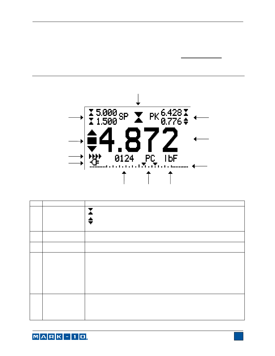
4.1 Home Screen
No. Name
Description
1 Tension
/
compression
indicator
- indicates a compression (push) direction
- indicates a tension (pull) direction
These indicators are used throughout the display and menu.
2 Peaks
The maximum measured compression and tension readings. These readings
are reset by pressing ZERO or by powering the gauge off and on.
3 Primary
reading The current displayed force reading. See Operating Modes section for
details.
4 Load
bar
Analog indicator to help identify when an overload condition is imminent. The
bar increases either to the right or to the left from the midpoint of the graph.
Increasing to the right indicates compression load, increasing to the left
indicates tension load. If set points are enabled, triangular markers are
displayed for visual convenience. This indicator reflects the actual load, which
may not correspond to the primary reading (depends on operating mode).
The ZERO key does not reset the load bar. See Operating Modes section for
details.
5 Units
The current measurement unit. Abbreviations are as follows:
lbF – Pound-force
ozF – Ounce-force
kgF – Kilogram-force
gF – Gram-force
1
2
3
4
5
6
7
8
9
10
11